
Torque Converter (page 2 of 4)
- Make
- Land Rover
- Model
- Range Rover L322 Range Rover System Description and Operation
- Section
- Description
AUTOMATIC TRANSMISSION – ZF 5HP24
44-2-12 DESCRIPTION AND OPERATION
The converter housing cover has four threaded bosses which provide for attachment of the engine drive plate which
is connected to the engine crankshaft. The threaded bosses also provide for location of special tools which are
required to removed the torque converter from the bell housing. With the impeller welded to the converter housing
cover, the impeller is therefore driven at engine crankshaft speed.
Impeller
The impeller outer body has a boss with two machined slots. The boss locates over the transmission input shaft and
the slots engage with two tangs on the fluid pump. This arrangement allows the fluid pump to be driven at engine
speed.
The impeller comprises a row of blades attached to the outer body. The root of the blades collect fluid which flows by
centrifugal force around the curved outer surface of the impeller to the tip of the blades.
Fluid Flow
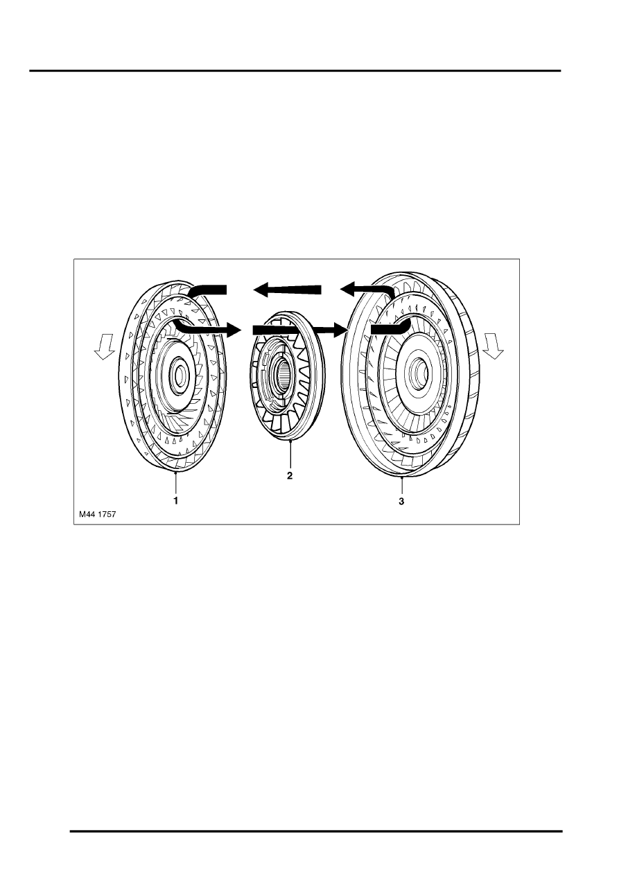
Typical torque converter shown
1 Turbine
2 Stator
3 Impeller
When the engine is running the rotating impeller acts as a centrifugal pump, picking up fluid at its centre and
discharging it at high velocity through the blades on its outer rim. The design and shape of the blades and the curve
of the impeller body cause the fluid to rotate in a clockwise direction as it leaves the impeller. This rotation improves
the efficiency of the fluid as it contacts the outer row of blades on the turbine.
The centrifugal force of the fluid leaving the blades of the impeller is passed to the curved inner surface of the turbine
via the tip of the blades. The velocity and clockwise rotation of the fluid causes the turbine to rotate.
Turbine
The turbine is similar in design to the impeller with a continuous row of blades. The fluid from the impeller enters the
turbine through the tip of the blades and is directed around the curved body of the turbine to the root of the blades.
The curved surface redirects the fluid back in the opposite direction to which it entered the turbine, effectively
increasing the turning force applied to the turbine from the impeller. This principle is known as torque multiplication.
Parts & tools for this job Staging For Land Rover Range Rover
- PARTTransmission filter kitSearch: Land Rover Range Rover transmission filter kit
- FLUIDAutomatic transmission fluidSearch: Land Rover automatic transmission fluid
- TOOLFluid transfer pumpSearch: fluid transfer pump
Links open Amazon search results in a new tab. As an Amazon Associate I earn from qualifying purchases.