
Instrument Pack CAN Messages
- Make
- Land Rover
- Model
- Freelander System Description and Operation
- Section
- Description › Instrument Pack CAN Messages
INSTRUMENTS
88-16
DESCRIPTION AND OPERATION
Diagnostics
A diagnostic socket allows the exchange of information between the instrument pack and TestBook or other
diagnostic tool. The diagnostic socket is located behind the centre console, in the passenger footwell.
The diagnostic socket is connected to the instrument pack on an ISO 9141 K Line. When the diagnostic mode is
accessed the LCD displays 'dIAg, which remains until the diagnostic mode is exited.
The instrument pack stores fault flags which can be retrieved using TestBook or any diagnostic tool using Keyword
2000 protocol.
Each fault stores two flags. The first flag (fault log) indicates that a fault has occurred with that function. This flag can
only be removed using a diagnostic tool.
The second flag (active fault) indicates that there is currently a fault with that function. This flag is only active while
the fault condition exists. Removal of the fault condition will clear the active fault flag.
Controller Area Network (CAN)
The CAN bus is a high speed broadcast network between the instrument pack, the ECM, the EAT ECU and the ABS
ECU, allowing fast exchange of data between the components every few microseconds.
The bus comprises two wires which are identified as CAN Low (L) and CAN High (H). The wires are twisted together
to minimise the electromagnetic interference (noise) produced from the CAN messages.
To prevent message errors from electrical reflections, 120
Ω
resistors are incorporated into the CAN wire terminals of
the ECM, ABS ECU, EAT ECU and the instrument pack.
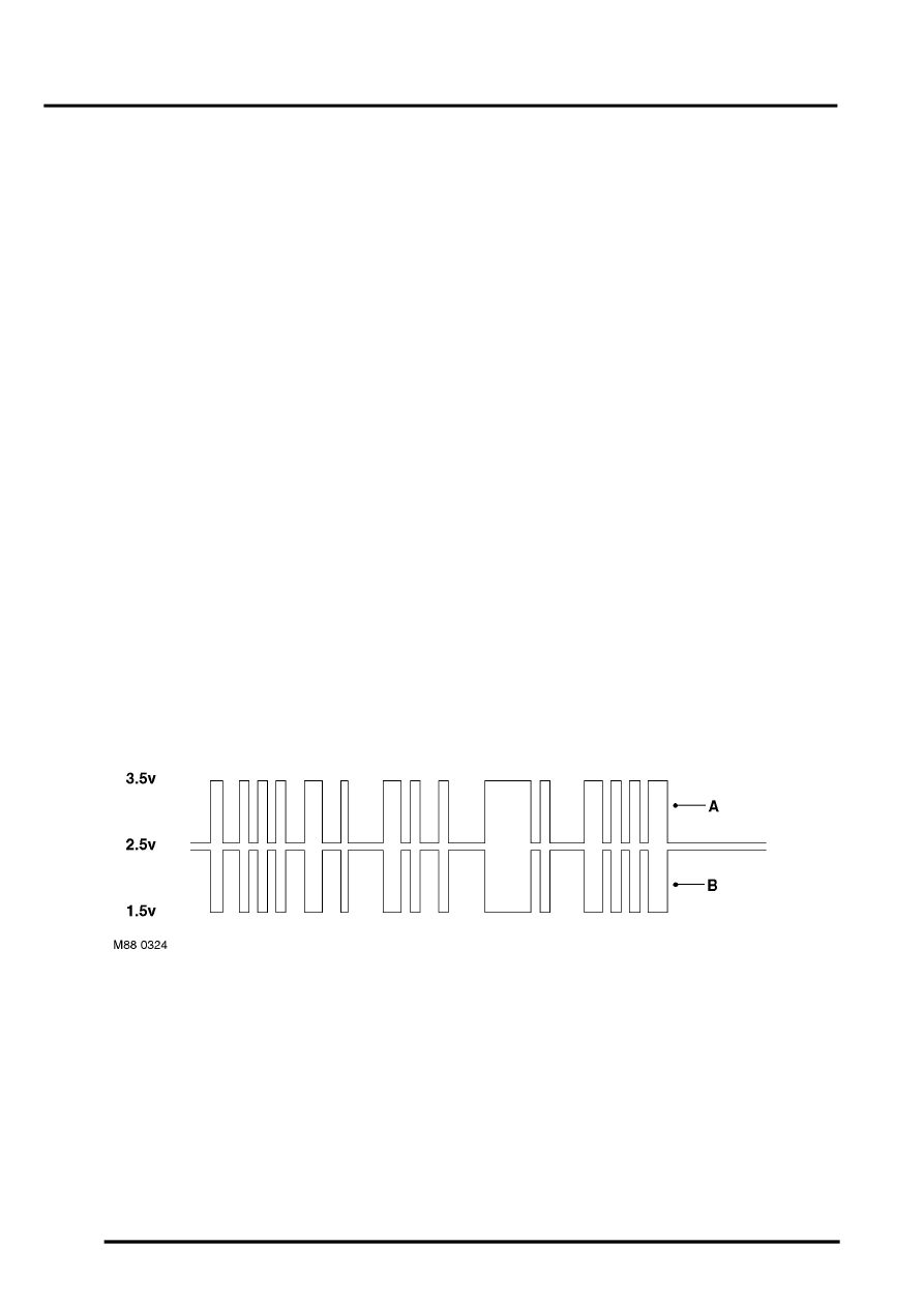
CAN messages consist of a signal which is simultaneously transmitted, in opposite phase, on both wires. CAN L
switches between 2.5 and 1.5 volts, while CAN H switches between 2.5 and 3.5 volts. This causes a potential
difference between the two lines to switch between 0 volt (logic 1) and 2 volts (logic 0) to produce the digital signal
message.
In the event of CAN bus failure, any of the following symptoms may be observed:
l
Tachometer, speedometer and temperature gauge will fail to operate
l
CAN controlled warning lamps will be inoperative.
CAN Bus Switching
A = CAN High
B = CAN Low
Instrument Pack CAN Messages
The instrument pack acts as a CAN gateway to other CAN controlled functions on the vehicle. The following table lists
signals which are routed through the gateway and translated to or from CAN as applicable. For further details about
the origins of these messages refer to the relevant section.
BRAKES, DESCRIPTION AND OPERATION, Description.
ENGINE MANAGEMENT SYSTEM - SIEMENS, DESCRIPTION AND OPERATION, Description.
AUTOMATIC GEARBOX - JATCO, DESCRIPTION AND OPERATION, Description.
Parts & tools for this job Staging For Land Rover Freelander
- TOOLTorque wrenchSearch: 3/8 inch torque wrench
- TOOLSocket setSearch: socket set metric
- BOOKHaynes manualSearch: Haynes manual Land Rover Freelander
Links open Amazon search results in a new tab. As an Amazon Associate I earn from qualifying purchases.