
CAN Bus Control Diagram
- Make
- Land Rover
- Model
- Freelander System Description and Operation
- Section
- CAN Bus Control Diagram
COMMUNICATION DATA BUSESCAN Bus Control Diagram
COMMUNICATION DATA BUSES
DESCRIPTION AND OPERATION
86-4-1
COMMUNICATION DATA BUSES
DESCRIPTION AND OPERATION
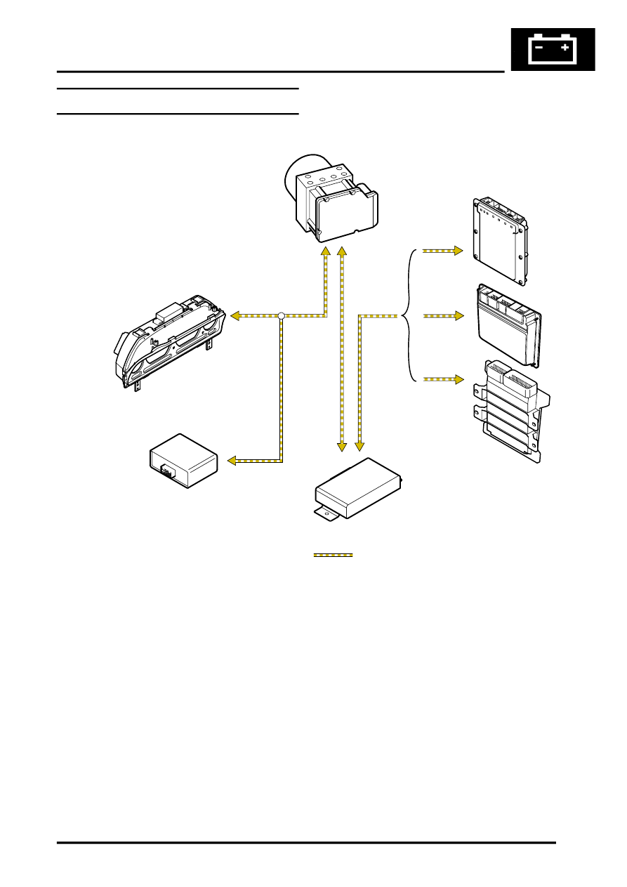
CAN Bus Control Diagram
Automatic Gearbox
D = CAN bus
1 Antilock brake system ECU
2 Engine control module (Td4)
3 Engine control module (non NAS KV6)
4 Engine control module (NAS KV6)
5 Electronic automatic transmission ECU
6 Cruise control interface unit
7 Instrument pack
M86 5380A
2
5
6
7
1
D
3
4
Parts & tools for this job Staging For Land Rover Freelander
- TOOLTorque wrenchSearch: 3/8 inch torque wrench
- TOOLSocket setSearch: socket set metric
- BOOKHaynes manualSearch: Haynes manual Land Rover Freelander
Links open Amazon search results in a new tab. As an Amazon Associate I earn from qualifying purchases.