
Distribution (page 2 of 2)
- Make
- Land Rover
- Model
- Freelander System Description and Operation
- Section
- Description
HEATING AND VENTILATIONDistribution · page 2 of 2
HEATING AND VENTILATION
DESCRIPTION AND OPERATION
80-9
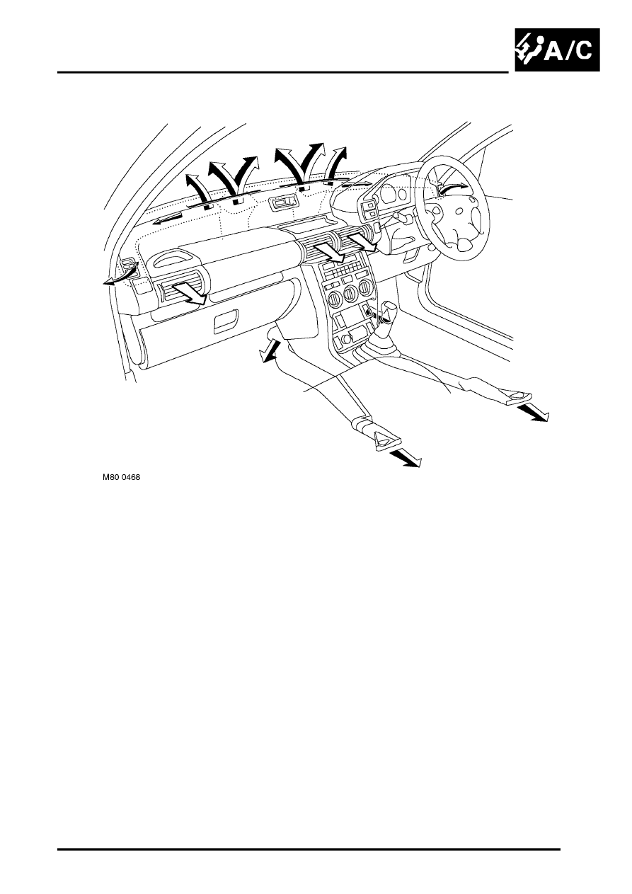
Fascia Outlets
Ducts
The rear footwell ducts extend along each side of the transmission tunnel and vent into the rear footwells from below
the front seats. The outer face level ducts attach to the underside of the fascia and connect to the vent assembly at
each end of the fascia. The windscreen/side window ducts connect to a duct integrated into the top of the fascia.
Vent Assemblies
The vent assemblies allow occupants to control the flow and direction of face level air. Each vent assembly
incorporates a thumbwheel to regulate flow and moveable vanes to control direction.
Parts & tools for this job Staging For Land Rover Freelander
- TOOLA/C manifold gauge setSearch: AC manifold gauge set
- TOOLUV leak detection kitSearch: AC UV leak detection kit
- PARTCabin filterSearch: Land Rover Freelander cabin filter
Links open Amazon search results in a new tab. As an Amazon Associate I earn from qualifying purchases.