
ROBOTIZED GEARBOX - Wiring diagram
- Make
- Lancia
- Model
- Ypsilon Factory Service Manual
- Year
- 2003–2011
- Section
- Vehicle electronic systems › ROBOTIZED GEARBOX - Wiring diagram
Wiring diagrams and electrical functionsROBOTIZED GEARBOX - Wiring diagram
ROBOTIZED GEARBOX - Wiring diagram
Wiring diagram
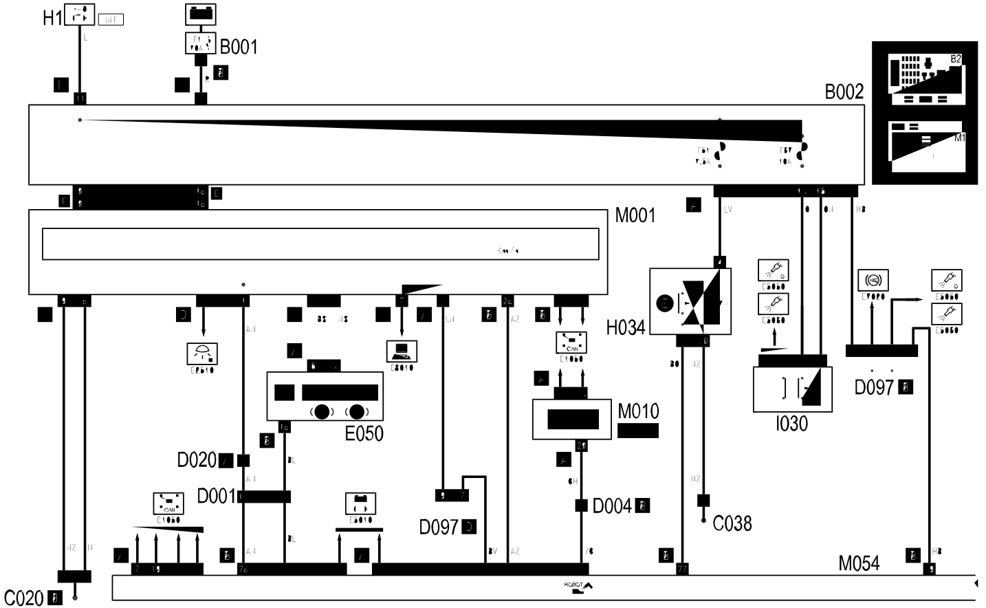
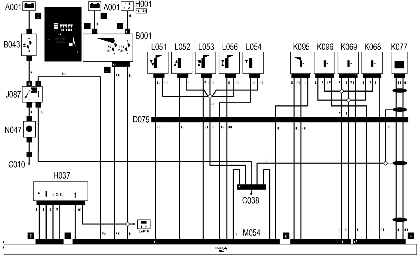
COMPONENTS
| Component code | Name | Assembly reference |
|---|---|---|
| A1 | Battery | 5530B |
| B1 | Engine compartment junction unit | 5505A |
| B2 | Junction unit under dashboard | 5505A |
| B43 | Robot gearbox supply fuse | |
| B43 | Robot gearbox supply fuse. | |
| C10 | Front left earth | |
| C20 | Passenger side dashboard earth | |
| C38 | Earth on tunnel | |
| D1 | Front / dashboard coupling | |
| D4 | Front / engine coupling | |
| D4 | Front/engine connection | |
| D20 | /Rear dashboard coupling | |
| D79 | Robot gearbox sensors coupling. | |
| D97 | Short circuiting coupling | |
| E50 | Instrument panel | 5560B |
| H1 | Ignition switch | 5520A |
| H34 | Robot gearbox auto function switch. | |
| H37 | Gear controls | |
| I30 | Brake pedal switch | 5550D |
| J87 | Robotized gearbox relay | |
| K68 | Speed selection potentiometer | |
| K69 | Gear shift potentiometer | |
| K77 | Gearbox input speed sensor | |
| K95 | Clutch position potentiometer | |
| K96 | Pressure sensor on transmission | |
| L51 | Solenoid 1 (gear engagement) | |
| L52 | Solenoid 2 (gear engagement) | |
| L53 | Solenoid 3 (gear engagement) | |
| L54 | Solenoid 4 (gear engagement) | |
| L56 | Clutch control solenoid | |
| M1 | Body computer | 5505A |
| M10 | Engine management control unit | |
| M10 | Engine management control unit | 1056B |
| M10 | Engine management control unit | 1060G |
| M54 | Robot gearbox control unit | |
| M54 | Robot gearbox control unit. | |
| N47 | Robot gearbox electric pump. |
Wiring diagram
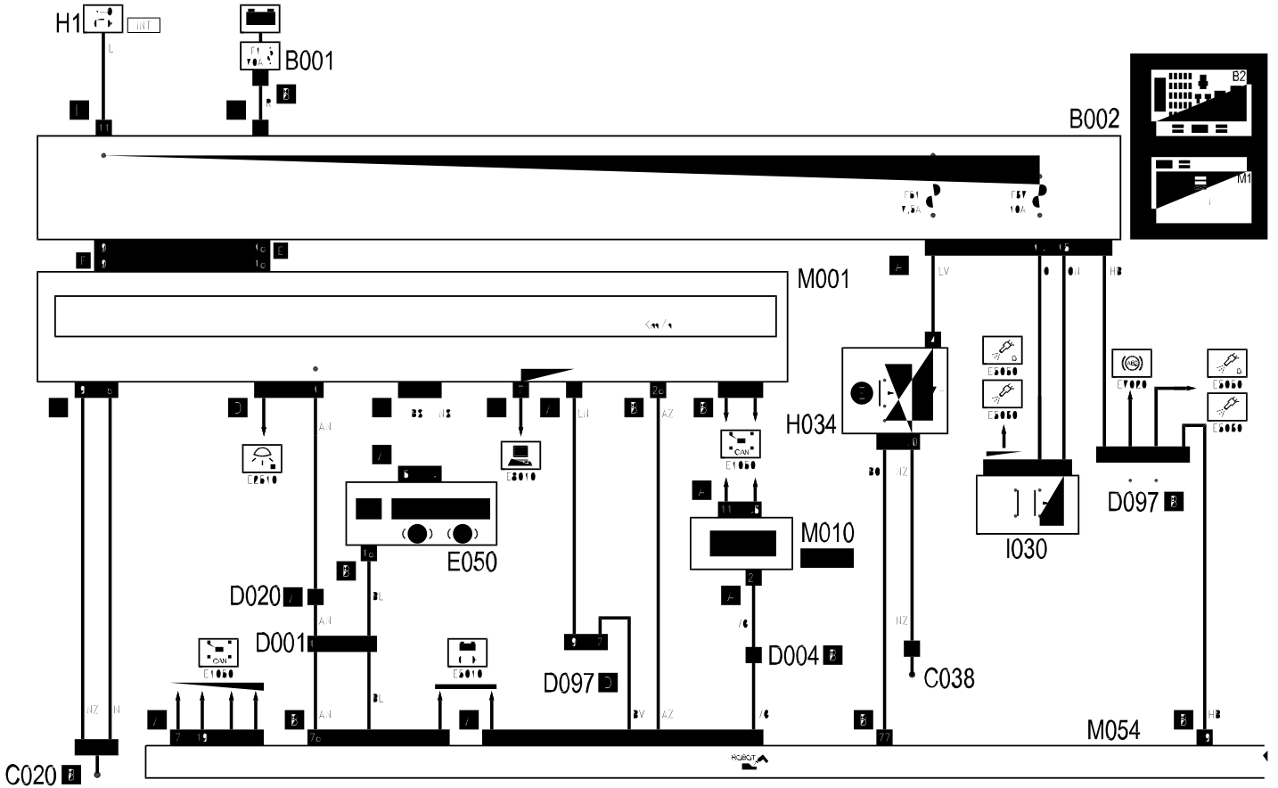
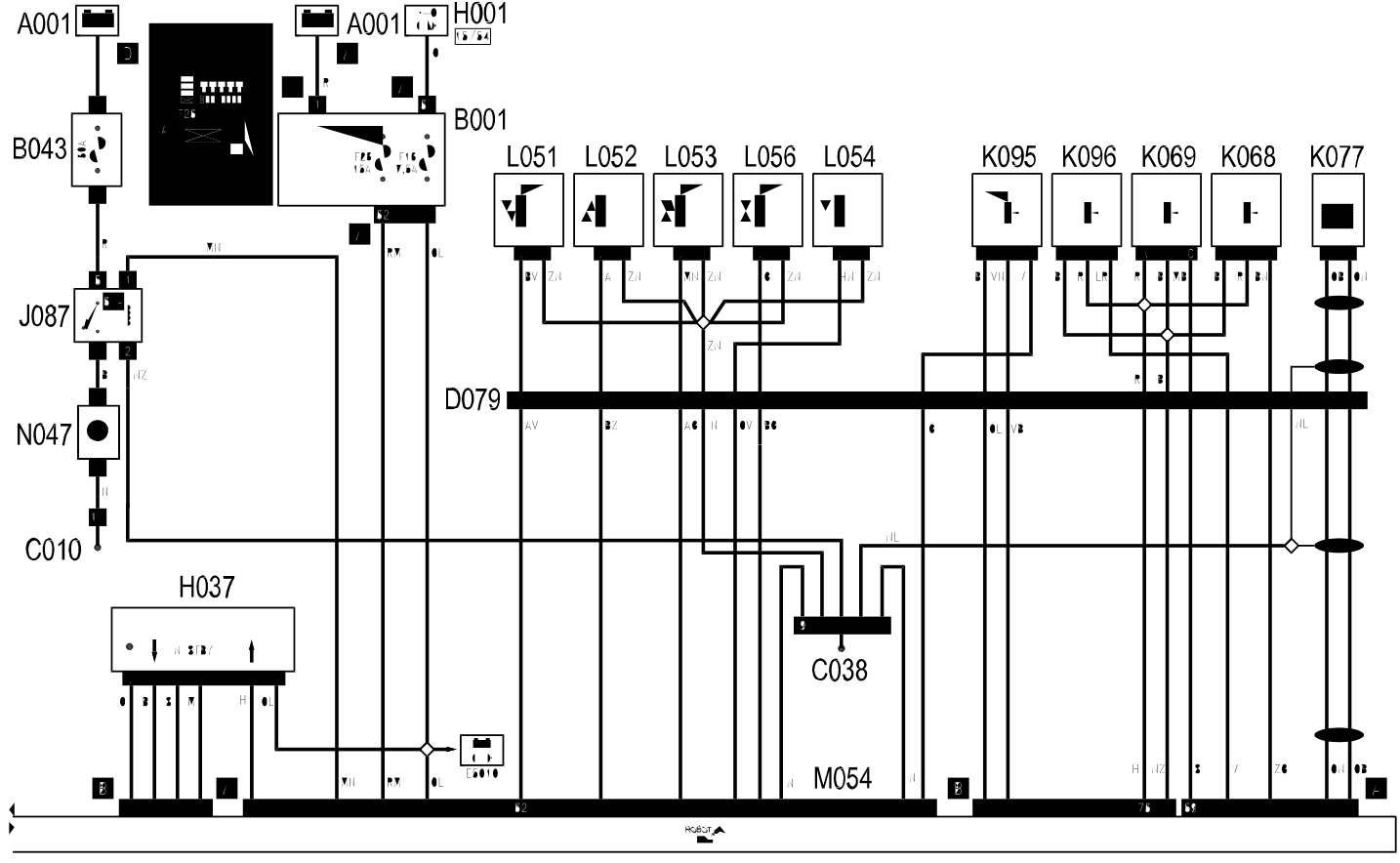
COMPONENTS
| Component code | Name | Assembly reference |
|---|---|---|
| A1 | Battery | 5530B |
| B1 | Engine compartment junction unit | 5505A |
| B2 | Junction unit under dashboard | 5505A |
| B43 | Robot gearbox supply fuse | |
| B43 | Robot gearbox supply fuse. | |
| C10 | Front left earth | |
| C20 | Passenger side dashboard earth | |
| C38 | Earth on tunnel | |
| D1 | Front / dashboard coupling | |
| D4 | Front / engine coupling | |
| D4 | Front/engine connection | |
| D20 | /Rear dashboard coupling | |
| D79 | Robot gearbox sensors coupling. | |
| D97 | Short circuiting coupling | |
| E50 | Instrument panel | 5560B |
| H1 | Ignition switch | 5520A |
| H34 | Robot gearbox auto function switch. | |
| H37 | Gear controls | |
| I30 | Brake pedal switch | 5550D |
| J87 | Robotized gearbox relay | |
| K68 | Speed selection potentiometer | |
| K69 | Gear shift potentiometer | |
| K77 | Gearbox input speed sensor | |
| K95 | Clutch position potentiometer | |
| K96 | Pressure sensor on transmission | |
| L51 | Solenoid 1 (gear engagement) | |
| L52 | Solenoid 2 (gear engagement) | |
| L53 | Solenoid 3 (gear engagement) | |
| L54 | Solenoid 4 (gear engagement) | |
| L56 | Clutch control solenoid | |
| M1 | Body computer | 5505A |
| M10 | Engine management control unit | |
| M10 | Engine management control unit | 1056B |
| M10 | Engine management control unit | 1060G |
| M54 | Robot gearbox control unit | |
| M54 | Robot gearbox control unit. | |
| N47 | Robot gearbox electric pump. |
Parts & tools for this job Staging For 2003 Lancia Ypsilon
- TOOLDigital multimeterSearch: automotive digital multimeter
- PARTAssorted fuse kitSearch: car fuse assortment kit
- TOOLWire crimper and connector kitSearch: wire crimper connector kit
Links open Amazon search results in a new tab. As an Amazon Associate I earn from qualifying purchases.