
Right hand cylinder head ignition coil - r+r
- Make
- Fiat
- Model
- Ulysse Factory Service Manual
- Year
- 2002–2010
- Section
- Engine ignition › Right hand cylinder head ignition coil - r+r
RIGHT HAND CYLINDER HEAD IGNITION COIL - R+R
Removing
- Disconnect the negative battery terminal.
| Description | Connector | |
|---|---|---|
| Battery |
Op. 5010B18 CLIMATE CONTROL UNIT AIR INTAKE - R.R.
Op. 5050B34 WINDSCREEN WIPER ARM/S COMPLETE WITH BLADE - R+R
Op. 7210E22 WINDSCREEN BASE TRIM
See in Op. 1088B10
Op. 1016A42 LEFT HAND CYLINDER HEAD IGNITION COIL COVER - R+R
Op. 1068A54 POTENTIOMETER ON ACCELERATOR CONTROL - R.R.
Op. 1048A47 SLEEVE FROM RIGID PIPE TO THROTTLE BODY - R R
Op. 1072B50 SLEEVES CONNECTING AIR CAPACITY BOX TO INLET MANIFOLD IS - R+R
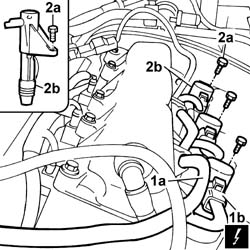
1. Release the cable loom (1a) from the anchorage points and disconnect the electrical conections (1b) from the ignition coils.
| Description | Connector | |
|---|---|---|
| 1 | Ignition coil |
2. Undo the fixing bolts (2a) and remove the ignition coils (2b) from the right cylinder head.
Removing
- Position the vehicle on the lift.
- Disconnect the negative battery terminal.
| Description | Connector | |
|---|---|---|
| Battery | A001B |
Op. 4450B04 RIGHT FRONT WHEEL R R
Op. 7055B54 UNDER-ENGINE GUARD - R R
Op. 7055B91 RIGHT FRONT WHEEL ARCH LINER - R.R.
Op. 5010B18 CLIMATE CONTROL UNIT AIR INTAKE - R.R.
Op. 5050B34 WINDSCREEN WIPER ARM/S COMPLETE WITH BLADE - R+R
Op. 7210E22 WINDSCREEN BASE TRIM
See in Op. 1088B10
Op. 4130B10 POWER STEERING FLUID RESEVOIR R R
Op. 4130B12 POWER STEERING FLUID RESERVOIR MOUNTING/BRACKETS - POSITION
Op. 1016A42 LEFT HAND CYLINDER HEAD IGNITION COIL COVER - R+R
See in Op. 1008C10
Op. 4410D16 BRACKET (ONE) RETAINING CHASSIS TO BODY - R R
See in Op. 1092G10
See in Op. 1092A10
See in Op. 1092G15
See in Op. 1092G21
See in Op. 1032D12
See in Op. 1008A46
See in Op. 1008B10
Op. 1092C14 POWER STEERING PUMP/SELF LEVELLING SUSPENSION PUMP PULLEY - R + R WITH BELT REMOVED
See in Op. 1032B44
Op. 1020D10 FRONT CRANK SHAFT OIL SEAL COVER - R + R AND REPLACE SEALS WITH TIMING BELT REMOVED
Refitting
- Position the ignition coils in the housings in the right cylinder head and tighten the fixing bolts to the recommended torque.
| Value - daNm | Fastening | Component | Ø  | |
|---|---|---|---|---|
| 0.8 | Bolts | RH CYLINDER HEAD IGNITION COILS |
- Connect the electrical connections to the ignition coils.
| Description | Connector | |
|---|---|---|
| Ignition coil |
- Secure the wiring harness to the anchorage points.
Op. 1072B50 SLEEVES CONNECTING AIR CAPACITY BOX TO INLET MANIFOLD IS - R+R
Op. 1048A47 SLEEVE FROM RIGID PIPE TO THROTTLE BODY - R R
Op. 1068A54 POTENTIOMETER ON ACCELERATOR CONTROL - R.R.
Op. 1016A42 LEFT HAND CYLINDER HEAD IGNITION COIL COVER - R+R
See in Op. 1088B10
Op. 7210E22 WINDSCREEN BASE TRIM
Op. 5050B34 WINDSCREEN WIPER ARM/S COMPLETE WITH BLADE - R+R
Op. 5010B18 CLIMATE CONTROL UNIT AIR INTAKE - R.R.
- Connect the negative battery terminal.
| Description | Connector | |
|---|---|---|
| Battery |
Op. 0010T21 COOLANT CHECK DENSITY AND TOP UP IF NECESSARY
Refitting
Op. 1020D10 FRONT CRANK SHAFT OIL SEAL COVER - R + R AND REPLACE SEALS WITH TIMING BELT REMOVED
See in Op. 1032B44
Op. 1092C14 POWER STEERING PUMP/SELF LEVELLING SUSPENSION PUMP PULLEY - R + R WITH BELT REMOVED
See in Op. 1008B10
See in Op. 1008A46
See in Op. 1032D12
See in Op. 1092G21
See in Op. 1092G15
See in Op. 1092A10
See in Op. 1092G10
Op. 4410D16 BRACKET (ONE) RETAINING CHASSIS TO BODY - R R
See in Op. 1008C10
Op. 1016A42 LEFT HAND CYLINDER HEAD IGNITION COIL COVER - R+R
Op. 4130B12 POWER STEERING FLUID RESERVOIR MOUNTING/BRACKETS - POSITION
Op. 4130B10 POWER STEERING FLUID RESEVOIR R R
See in Op. 1088B10
Op. 7210E22 WINDSCREEN BASE TRIM
Op. 5050B34 WINDSCREEN WIPER ARM/S COMPLETE WITH BLADE - R+R
Op. 5010B18 CLIMATE CONTROL UNIT AIR INTAKE - R.R.
Op. 7055B91 RIGHT FRONT WHEEL ARCH LINER - R.R.
Op. 7055B54 UNDER-ENGINE GUARD - R R
Op. 4450B04 RIGHT FRONT WHEEL R R
- Connect the negative battery terminal.
| Description | Connector | |
|---|---|---|
| Battery | A001B |
Op. 0010T70 POWER ASSISTED STEERING FLUID - REPLACE
Op. 0010T21 COOLANT CHECK DENSITY AND TOP UP IF NECESSARY
- Remove the vehicle from the lift.
Removing
Op. 5530B56 BATTERY DRIP TRAY COVER - R.R.
Disconnect the negative battery terminal.
Op. 1088B10 ENGINE COOLING TANK - R + R
Op. 7055B54 UNDER-ENGINE GUARD - R R
Op. 4450B04 RIGHT FRONT WHEEL R R
Op. 7055B91 RIGHT FRONT WHEEL ARCH LINER - R.R.
Op. 4410D16 BRACKET (ONE) RETAINING CHASSIS TO BODY - R R
[Right front]
Op. 1092G10 SINGLE ENGINE BELT R R
Op. 1092A10 CRANKSHAFT SERVICES PULLEY - R.R.
Op. 1032D12 TIMING SYSTEM PROTECTIVE COVER(S) - R + R
Op. 1032B10 TOOTHED TIMING BELT - R + R FOR TIMING ADJUSTMENT OR REPLACEMENT
Op. 1032B44 TOOTHED DRIVE PULLEY - R + R WITH TIMING BELT REMOVED
Op. 1084A16 OIL DIP STICK PIPE - R R
Op. 1020A20 CRANK CASE OIL SUMP - R + R CLEAN SEALS FOR SEALANT APPLICATION
Op. 1084A16 OIL DIP STICK PIPE - R R
Op. 1020A20 CRANK CASE OIL SUMP - R + R CLEAN SEALS FOR SEALANT APPLICATION
Op. 1084B28 ENGINE OIL INTAKE PUMP - R + R WITH CRANKCASE SUMP REMOVED
Op. 1092G15 ENGINE COMPONENT SINGLE BELT MOBILE TEMPERATURE - R RWITH BELT REMOVED
Op. 1032C30 FIXED TIMING SYSTEM TENSIONER - R + R WITH TIMING BELT REMOVED
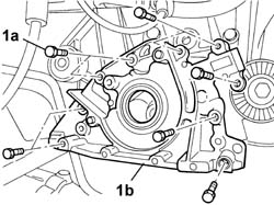
1. Undo the fixing bolts (1a) and remove the crankshaft front oil seal cover and oil pump on the timing side crankshaft (1b).
Refitting
- Remove the oil sealing ring from its seat on the front cover.
Because the oil seal must always be replaced, it may be destroyed when it is removed.
- Apply sealant to the front cover.
| Description | Q.ty | Component | Type | Classification | |
|---|---|---|---|---|---|
| DOW CORNING 7091 | FRONT COVER CRANKSHAFT | Silicon sealant |
- Fit the cover and tighten the bolts to the recommended torque.
| Value daNm | Fastening | Component | Ø | |
|---|---|---|---|---|
| 0.9 | Bolt | FRONT COVER CRANKSHAFT |
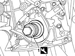
1. Fit the seal using the tool.
| Description | Code | Function | |
|---|---|---|---|
| 1 | Fitting tool | 1.870.883.000 | Fitting crankshaft front oil seal |
Op. 1032C30 FIXED TIMING SYSTEM TENSIONER - R + R WITH TIMING BELT REMOVED
Op. 1092G15 ENGINE COMPONENT SINGLE BELT MOBILE TEMPERATURE - R RWITH BELT REMOVED
Op. 1084B28 ENGINE OIL INTAKE PUMP - R + R WITH CRANKCASE SUMP REMOVED
Op. 1020A20 CRANK CASE OIL SUMP - R + R CLEAN SEALS FOR SEALANT APPLICATION
Op. 1084A16 OIL DIP STICK PIPE - R R
Op. 1032B44 TOOTHED DRIVE PULLEY - R + R WITH TIMING BELT REMOVED
Op. 1032B10 TOOTHED TIMING BELT - R + R FOR TIMING ADJUSTMENT OR REPLACEMENT
Op. 1032D12 TIMING SYSTEM PROTECTIVE COVER(S) - R + R
Op. 1092A10 CRANKSHAFT SERVICES PULLEY - R.R.
Op. 1092G10 SINGLE ENGINE BELT R R
Op. 4410D16 BRACKET (ONE) RETAINING CHASSIS TO BODY - R R
[Right front]
Op. 7055B91 RIGHT FRONT WHEEL ARCH LINER - R.R.
Op. 4450B04 RIGHT FRONT WHEEL R R
Op. 7055B54 UNDER-ENGINE GUARD - R R
Op. 1088B10 ENGINE COOLING TANK - R + R
Op. 0010T21 COOLANT CHECK DENSITY AND TOP UP IF NECESSARY
Connect the negative battery terminal.
Parts & tools for this job Staging For 2002 Fiat Ulysse
- PARTSpark plugsSearch: Fiat Ulysse 2002 spark plugs
- TOOLSpark plug socketSearch: spark plug socket
- TOOLSpark plug gap toolSearch: spark plug gap tool
Links open Amazon search results in a new tab. As an Amazon Associate I earn from qualifying purchases.