
Left hand cylinder head ignition coil - r+r
- Make
- Fiat
- Model
- Ulysse Factory Service Manual
- Year
- 2002–2010
- Section
- Engine ignition › Left hand cylinder head ignition coil - r+r
LEFT HAND CYLINDER HEAD IGNITION COIL - R+R
Removing
See in Op. 1032B44
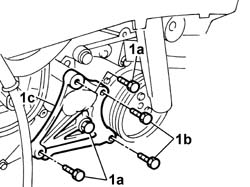
1.. Undo the fixing bolts (1a) and (1b), then remove the air conditioning compressor mounting bracket (1c).
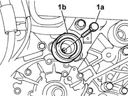
1. Undo the fixing bolt (1a) and remove the fixed timing belt tensioner (1b).
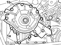
1. Undo the fixing bolts (1a) and remove the front cover (1b).
Removing
Op. 5010B18 CLIMATE CONTROL UNIT AIR INTAKE - R.R.
Op. 1016A42 LEFT HAND CYLINDER HEAD IGNITION COIL COVER - R+R
- Disconnect the negative battery terminal.
| Description | Connector | |
|---|---|---|
| Battery |
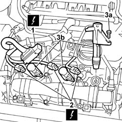
1. Disconnect the electrical connector for the coil/injector cable loom.
| Description | Connector | |
|---|---|---|
| 1 | Coil/injector coupling |
2. Disconnect the electrical connections for the ignition coils.
| Description | Connector | |
|---|---|---|
| 2 | Ignition coil |
3. Undo the fixing bolts (3a) and remove the ignition coils (3b) from the left cylinder head.
Refitting
- Remove the oil sealing ring from its seat on the front cover.
| Value - daNm | Fastening | Component | Ø | |
|---|---|---|---|---|
| 0.5 | Bolts | ENGINE OIL SEAL FRONT COVER |
Because the oil seal must always be replaced, it may be destroyed when it is removed.
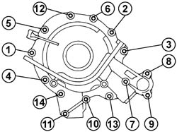
- Position the front cover and fully tighten the fixing bolts by hand.
- Pre-tighten the fixing bolts to the recommended torque, following the order illustrated in the diagram below.
- Tighten the fixing bolts, following the order illustrated, until all the bolts are at the recommended torque.
| Value - daNm | Fastening | Component | Ø | |
|---|---|---|---|---|
| 0.8 | Bolts | ENGINE OIL SEAL FRONT COVER |
- Resume the tightening of the fixing bolts, following the order illustrated, until all the bolts are at the recommended torque.
| Value - daNm | Fastening | Component | Ø | |
|---|---|---|---|---|
| 0.8 | Bolts | ENGINE OIL SEAL FRONT COVER |
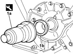
1. Refit a new oil seal (1b) on the crankshaft front cover using the tool (1a).
| Description | Code | Function | |
|---|---|---|---|
| 1a | Fitting tool | 1.870.900.100 | Engine oil front cover oil seal |
Refitting
- Position the ignition coils in the housings in the left cylinder head and tighten the fixing bolts to the recommended torque.
| Value - daNm | Fastening | Component | Ø | |
|---|---|---|---|---|
| 0.8 | Bolts | LH CYLINDER HEAD IGNITION COILS |
- Connect the electrical connections to the ignition coils.
| Description | Connector | |
|---|---|---|
| Ignition coil |
- Connect the electrical connector for the coil/injector cable loom.
| Description | Connector | |
|---|---|---|
| Coil/injector coupling |
Op. 1016A42 LEFT HAND CYLINDER HEAD IGNITION COIL COVER - R+R
Op. 5010B18 CLIMATE CONTROL UNIT AIR INTAKE - R.R.
- Connect the negative battery terminal.
| Description | Connector | |
|---|---|---|
| Battery |
1. Check that the locating dowels are fitted on the engine block.
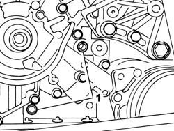
- Position the air conditioning compressor mounting bracket and tighten the fixing bolts to the recommended torque.
| Value - daNm | Fastening | Component | Ø | |
|---|---|---|---|---|
| 0.8 | Bolt | AIR CONDITIONING COMPRESSOR MOUNTING BRACKET AIR |
- Place the tensioner roller in position and tighten the fixing bolt to the recommended torque
| Value - daNm | Fastening | Component | Ø | |
|---|---|---|---|---|
| 0.8 | Bolt | TIMING DRIVE BELT FIXED TENSIONER (ONE) - R.R. |
Apply a locking compound to the threaded part of the screw.
See in Op. 1032B44
Parts & tools for this job Staging For 2002 Fiat Ulysse
- PARTSpark plugsSearch: Fiat Ulysse 2002 spark plugs
- TOOLSpark plug socketSearch: spark plug socket
- TOOLSpark plug gap toolSearch: spark plug gap tool
Links open Amazon search results in a new tab. As an Amazon Associate I earn from qualifying purchases.