
Construction specifications
- Make
- Fiat
- Model
- Ulysse Factory Service Manual
- Year
- 2002–2010
- Section
- General › Construction specifications
CONSTRUCTION SPECIFICATIONS
INTRODUCTION
The vehicle is equipped with a braking system designed to achieve:
- a high level of efficiency as an active safety feature
- durability and reliability
- excellent flexibility
The system is the servo-assisted hydraulic type with two independent cross-over circuits (each circuit acting on one front wheel and the diametrically opposite rear wheel) to ensure braking on both sides of the vehicle if there is a failure in one of the circuits. It is equipped with sophisticated auxiliary electronic systems:
- EBD (Electronic Brakeforce Distribution) function
- HBA (Hydraulic Brake Assistance)
- TC + ASR (Traction control) (Anti Slip Regulation)
- MSR
- ESP (Electronic Stability Program)
- ABS (Anti-Lock Braking System)
The 2.0 16V petrol and 2.0 16v JTD versions have ABS fitted as standard whilst the top of the range 2.2 16V ITD and 3.0 24V versions have the ESP fitted as standard.
ABS (Anti-Lock Braking System)
Structure
ABS prevents the wheels from locking allowing braking to be modulated irrespective of the level of each wheel, metering the pressure at the brackets.
The ABS consists of:
- an electronic control unit incorporated in the electro-hydraulic control unit (with the whole assembly known as the Brake Node NFR)
- a hydraulic control unit that modulates braking pressure by means of eight solenoids, two for each wheel
- four active type sensors that detect the angular speed of the wheels
- wiring with specific connector
Using the speed information received from each wheel, the electronic node controls the subsequent pressure maintenance, pressure decrease and pressure increase stages, if necessary. Maintaining the slipping rate at between 10 and 30% during braking makes it possible to ensure optimum stopping distances and preserve good directional stability.
Operation
All versions of the vehicle are fitted as standard with a Bosch 5.7 anti-lock braking system with 4 active sensors and 4 channels with electronic brakeforce distribution (EBD) incorporated. The active safety features are:
- guaranteeing maximum braking action for each wheel within the locking limit
- safeguarding the directional stability of the vehicle, within the locking limit
- quickest possible reponse
- the capacity to automatically adapt to the most diverse operating conditions
The innovative feature of the active sensors lies in the fact that the signal received by each wheel is processed directly by the sensor rather than being sent to the NFR. The main advantages of this solution are basically that the system intervenes immediately because it is able to read speed signals close to zero (the passive sensors are restricted to speeds above 4 km/h). A further advantage of the system is the reduced sensitivity to outside electromagnetic interference caused by electromagnetic fields present in towns and places of high technological and industrial density plus the fact that it is not susceptible to interference produced by the heating of the road surface (used in some North European countries).
Brake Node NFR (ABS version)
Specifications and operation
The brake node is divided into two sections - an electronic node and an electro-mechanical control unit
The electro-mechanical control unit has the task of modulating the pressure of the fluid at the brake calipers via solenoid valves with the following operating stages:
- brake fluid pressure increase
- brake fluid pressure maintenance
- brake fluid pressure discharge
The electro-hydraulic control unit consists of:
- eight 2-way solenoid valves
- a dual circuit recovery pump
- two low pressure accumulators
- two high pressure accumulators
The electronic node has the following functions:
- acquiring the data coming from the wheel sensors
- memorizing the control parameters defined during the vehicle P.D.I.
- processing the data acquired
- checking the braking process, preventing the wheels from locking
- memorizing the fault codes and activating the ABS and EBD warning lights
- transmitting and receiving data via the CAN line
- detecting faults in the braking system components
The operation of the ABS is illustrated in the diagram below
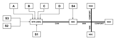
- A,B,C,D - Anti-lock brake sensors for the wheels
- S1 - Brake fluid level signal
- S2, S3 - Left and right front brake pad wear signal
- NFR (ABS) - Brake node with ABS
- S4 - Stop signal switch
Self-diagnosis
The basic processing of the NFR software consists of detecting all the problems which could occur.
The management of the faults is carried out at three safety levels:
- Checking the signals whilst the vehicle is driving (presence, value interval and dispersion)
- Analytical redundance (consistency of the signals starting with one model).
- Active tests (operation of the pre-loading pump and hydraulic lock during initialization and at the start of driving + slewing sensor test by the brake node).
The role of levels 1 and 2 is to check basic operation, whilst level 3 is designed to prevent untimely activation of the adjustment which could be caused following static interference or as a result of a sensor fault.
The device carries out checks of a different nature ranging from short circuiting and electrical faults to mechanical problems.
If there is a fault, the system only puts the functions involved out of commission, guaranteeing the mechanical braking function.
Electronic Brake Force Distribution (EBD)
This is the distribution of the brake force between the front and rear wheels; its intevention improves braking efficiency ensuring optimum balance. The incorporation of the EBD device in the ABS guarantees the optimum behaviour of the vehicle during braking through:
- improved brakeforce distribution
- adjustments adapted to the actual wheel grip conditions and efficiency of the pads
- continuous monitoring of the efficiency of the system
- maintaining the adjustment over a period of time
- a reduction in the temperature of the front brakes and the force required at the brake servo
Assisted emergency braking
The assisted braking system is either the hydraulic type HBA (Hydraulic Brake Assistance) or the mechanical type MBA (Mechanical Brake Assistance). In both cases they are systems that automatically increase braking pressure in emergency situations. In effect, in critical conditions, when the driver operates the brake pedal decisively, the system intervenes on the braking circuit, increasing braking pressure to ensure that the vehicle stops as quickly as possbile. The system is calibrated at the pedal operating speed and intervenes when the speed of the pedal vpedal > 450mm/s.
The two systems behave in the same way, the only difference being that the pressure increase setting in one case is regulated by the ESP software and in the other case in a mechanical fashion.
Traction control and anti-slip system (TC and ASR)
The ASR system is available incorporated in the ESP for automatic traction control. The ASR (Anti-Slip Regulation) system prevents the drive wheels from slipping by reducing the excess engine torque on the basis of the grip coefficient for the available road surface. The ASR control unit calculates the slipping of the drive wheels using the difference between the front and rear wheel speeds measured by the ABS sensors.
Depending on the driving situation, two different control systems can be activated:
- If there is a request for excess power with the drive wheels slipping, the ASR reduces the torque through intervention on the throttle, the advance and the fuel supply for petrol engines or by adjusting the injection on diesel versions.
- If only one wheel is slipping, the TC (Traction Control) system intervenes automatically, braking the wheel without the driver operating the brake pedal, producing a locking effect similar to that of a self-locking differential.
The effect of less stress for the mechanical traction components (differential and gearbox) achieved by controlling traction at low speeds is also important.
Engine drive regulation. (MSR)
This system regulates engine braking torque when changing down: in the case of a rapid gear change to a lower gear, the MSR system ("Motor Scleppmoment Regelung") intervenes, restoring engine torque, preventing the wheel from locking which, especially in poor grip conditions, could lead to a loss in vehicle stability.
ESP
General remarks
The ESP (Electronic Stability Program) (fitted as standard on 2.2 16V JTD versions) is an active safety system for controlling the vehicle during dynamic manoeuvres. This system keeps the vehicle stable during sudden manoeuvres, improving active safety, especially on slippery surfaces. In effect, the ESP reacts quickly to both oversteer and understeer, returning the vehicle to a stable condition and allowing the driver to keep full control.
When the ESP is activated, the amber coloured warning light flashes.
Switching ESP/ASR off.
The ESP is automatically switched on when the ignition is turned ON.
The ESP system can be switched off by the driver, by pressing a button located in the lower part of the dashboard, driver's side, thereby allowing the vehicle to be used in certain particularly serious situations.
The switching off of the ESP is signalled by the amber coloured warning light on constantly and by a message in the display / NSC screen: "ESP switched off".
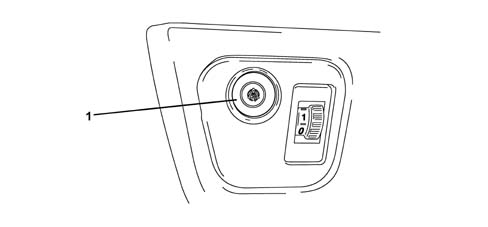
- 1 ESP/ASR disabling button
When the ESP is switched off the ASR is also deactivated as a result of which, when driving on snow-covered roads, with snow chains fitted, it might also be useful to switch the ASR off; in effect, under these circumstances the slipping of the drive wheels during take off allows better traction.
The ESP off condition is cancelled both when the speed of the vehicle is above 30 km/h and after the ignition is switched ON.
Operation
The system detects the state of the vehicle (lateral acceleration, angular speed, grip on the ground) and, if it feels that the vehicle is close to an unstable condition (skidding, understeer, oversteer), it acts on the drive torque and applies suitable differentiated braking action at each of the four wheels.
Control of the direction takes place by exploiting the longitudinal and transverse grip of the tyre: the different braking on the two sides of the vehicle produces a straightening torque (slewing control).
The management of the ESP function is entrusted to the NFR (brake node) which, by processing the figures acquired from the sensors (steering angle sensor, lateral acceleration sensor / slewing sensor, wheel rpm sensors, braking system pressure sensor), monitors the dynamic control parameters (wheel slipping, slewing speed, geometry angle) and corrects the trajectory of the vehicle producing a stabilizing effect.
The management of the system is illustrated below.
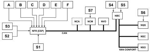
- A,B,C,D - Anti-lock brake sensors for the wheels
- E - Slewing and acceleration sensor
- F - Braking pressure sensor incorporated in the hydraulid unit
- S1 - Brake fluid level signal
- S2, S3 - Brake pad wear signal
- S4 - Main stop signal
- S5 - Parking brake signal
- S6 - ESP/ASR disabling button
- S7 - Accelerator pedal potentiometer signal
- NFR (ESP) - Brake node (electronically and electro-hydraulically controlled node) with ESP system
In accordance with the previous table, the system interacts with:
- the CAN line (to converse with the engine management node (NCM), automatic transmission node (NCA), where fitted, etc.)
- the specific brake pump, which produces the pressure required to act on the brakes
- the electronic throttle (for dialogue between the NFR and NCM nodes)
- the instrument panel Node, the milometer warning lights Node with active type warning lights and with the multi-function screen node.
Operating strategies
As stated previously, in addition to controlling the slipping of the vehicle in a lengthwise direction, the ESP system also controls slipping in a sideways direction and, as a result, controls the lateral stability of the vehicle.
The lateral stability of a vehicle depends on the reaction of the tyres to lateral forces and the adhesion force of the wheel with the road surface.
The adhesion force of a wheel depends on the vertical load which depends on the situation the wheel finds itself in (resting or no load) and on the friction coefficient which depends on the road surface and tyre conditions.
When the vehicle is travelling in a straight line, the lateral forces do not really have an effect unless outside factors that increase its intensity intervene (e.g. a gust of wind or a change to a different surface), unlike when driving round a bend where there is a strong increase in lateral forces due to the increase in centrifugal force.
The action of the lateral forces produce a variation in the drift angle of the wheels and, consequently, a variation in the axle drift (the drift angle refers to the difference between the desired route and the effective route).
The lateral forces cannot act in the same way on all four wheels because they are not all in the same load conditions. The load for each wheel: depends on:
- acceleration (lightening of the front axle and loading of the rear axle)
- braking (loading of the front axle and lightening of the rear axle)
- bend to the right/left (loading or the outer wheels and lightening of the inner wheels)
- accelerating/decelerating round a bend (combination of the cases mentioned above).
It is obvious that if the lateral forces acting on the individual wheels vary, there will also be a variation in the resulting forces acting on the vehicle axles. This means that the lateral forces acting on the front axle overcoming those acting on the rear axle and viceversa results in a rotation (moment) in relation to the vehicle's vertical axis (slewing axis).
The moment of slewing affects the behaviour of the vehicle producing either understeer or oversteer.
Understeer for a vehicle is when, with increasing lateral acceleration, the drift angle for the front axle increases greatly compared with that of the rear axle. In this case the vehicle, when driving round a bend, tends to coincide with the tangent of the actual bend.
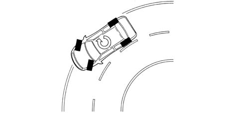
Oversteer for a vehicle is when, with increasing lateral acceleration, the drift angle for the rear axle increases greatly compared with that of the front axle. In this case the vehicle has a tendency to overturn.
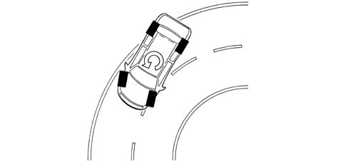
In order to keep the effect of lateral forces under control and limit the slewing moment, the A.B.S. must firstly calculate the behaviour of vehicle set by the driver using:
- steering wheel angle sensor
- accelerator pedal position
- brake circuit pressure
after which the brake node (NFR) should check the actual behaviour of the vehicle through:
- the wheel sensors (vehicle speed/wheel speed),
- lateral acceleration sensor / slewing sensor.
As can be deduced from what has been said earlier, the node is capable of:
- detecting actions carried out by the user, in effect, through the position of the steering wheel it checks the number of degrees (wide radius or narrow radius bends) and the speed for rotating the steering wheel (sharp or gentle rotations) and, using the position of the throttle and the brake pressure when accelerating or braking, how the user is taking the bend or deviating from the straight path.
- detecting the actual behaviour of the vehicle given the environmental variables, e.g. slippery surface, reaction of the vehicle to incorrect manoeuvres by the user, etc., in order to identify the moment of slewing and the lateral sliding of the axles via the sensors on the four wheels and the slewing/lateral acceleration sensor.
These two operations are necessary to superimpose the mathematical model analyzed in the node on the actual behaviour of the vehicle in order to determine the corrective measures to be implemented through the brakes and the engine.
Understeer round bends
The system verifies the presence of understeer (mainly from the drift of the front axle), corrects the behaviour of the vehicle, braking the inner wheels round the bend in order to create an opposing moment which will lead the vehicle towards the centre of the bend and, possibly, reducing the drive torque.
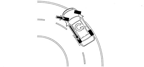
Oversteer round bends
In the presence of understeer (mainly from the drift of the rear axle) the NFR corrects the behaviour of the vehicle, braking the outer front wheel round the bend in order to create an opposite slewing moment, if necessary increasing the drive torque.
The system intervenes before the oversteer and understeer values are too high in order to limit the corrective measures that have to be taken which could make handling difficult.
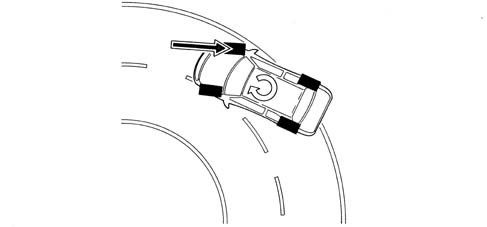
Sharp variations from the straight path (slalom/overtaking)
In the case of sharp variations from the path (e.g. overtaking, slalom), the system identifies possible oversteer and understeer conditions and corrects the path of the vehicle acting as described in the cases mentioned previously.
Sharp variation from the straight path (driving on different surfaces)
The electronic node is capable of detecting deviations in the path and the prevalence of axle drift, correcting the path through suitable action on the brakes and the engine.
Sharp acceleration/deceleration
The system uses the A.S.R./M.S.R. strategy also controlling the lateral acceleration of the vehicle and, as a result, regulating the action on the front and rear brakes and on the engine torque in a more complete way than on vehicles with ASR only.
Steering sensor
The steering angle sensor has the task of measuring the angles in degrees and the rotation speed of the steering wheel and making these figures available via the Bodywork VAN network (NVO).
Operation
The diagram shows a section of the steering column switch unit and toothed wheels.
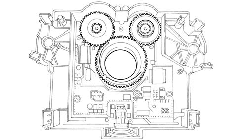
The sensor, incorporated in the steering column switch unit, comprises three toothed wheels. One main wheel fitted on the column axis which rotates when the steering wheel is operated. Two wheels, each fitted with a magnet that are activated by the main wheel and have one tooth different in relation to each other. This difference is translated into a different rotation speed for the wheels. In order to measure the steering wheel angle, the sensor needs a reference corresponding to an angle of zero. This reference is not determined by positioning the system during the fitting stage, but requires the sensor to be calibrated in the factory so that this equipment is operational, neutralizing the lighting up of the ASR/ESP failure warning light.
It is incorporated in the toe in bench at the end of the assembly line.
The sensor measures the following via internal electronics:
- the angular position of the steering column
- the rotation speed of the steering column.
This information is processed directly by the sensor and is made available at the brake node via the network.
The sensor has an autodiagnostic function and is capable of carrying out a check on the plausibility of the information processed.
Slewing/lateral acceleration sensor
Composition and operation
The sensor consists of sensitive elements which detect slewing and lateral acceleration and an electronic management function.
The sensor is located in the centre of gravity area on the tunnel between the two front seats near the Air Bag node (see diagram).
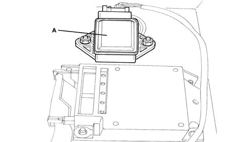
- A - Slewing/lateral acceleration sensor
The sensor has the task of detecting rotation on the vehicle's vertical axis (slewing) and measuring lateral acceleration.
ESP system brake node (NFR)
The electro-hydraulic unit located in the engine compartment on the left front wheel arch comprises an electronic node and an electro-hydraulic control unit. The entire system is known as the NFR (brake node).
The technology is identical to the ABS / ASR system and the operating principle is the same but this system includes 12 solenoid valves (4 inlet solenoid valves, 4 switching solenoid valves and 4 pre-loading solenoid valves), 2 accumulators and a dual acting piston pump.
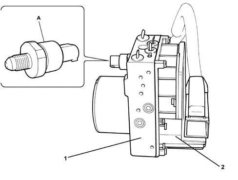
- 1 Electro-hydraulic control unit
- 2 Electronic control node
- A - Pressure sensor
Thanks to the peripheral activators and sensors, the electronic unit analyzes the information concerning the trajectory of the vheicle and implements the corrective measures, whilst the electro-hydraulic control unit has the function of modulating the pressure of the fluid at the brake calipers through the solenoid valves in the following stages:
- brake fluid pressure increase
- brake fluid pressure maintenance
- brake fluid pressure decrease.
Anti-lock braking system active sensors
Composition and operation
Resistive, mangetic type inductive sensors which measure the speed of each of the vehicle's wheels through a toothed wheel are used to acquire the speed of the wheels.
The sensor consists of a permanent magnet and a winding. A toothed wheel, in one piece with the vehicle wheel, slides in front of the sensor, the magnetic flow varies and produces an alternating voltage in the winding whose frequency and amplitude are proportional to the rotation speed of the toothed wheel as illustrated in the diagram.
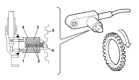
- 1 permanent magnet
- 2 magnetic poles
- 3 winding
- 4 sensor casing
- 5 toothed wheel
- 6 induced magnetic field
System warning lights
The diagram shows the warning lights at the milometer warning lights node NSO
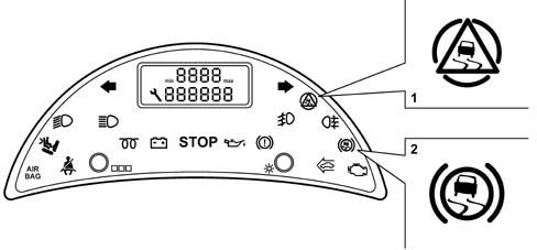
- 1 ESP warning light
- 2 ABS warning light
ESP/ASR intervention/fault display
The intervention of the ESP system is shown by the special warning light in the milometer warning lights Node (NSO) flashing (5 Hz d.c. 50%).
If there is a fault or in the case of manual disablement, the ESP system switches off automatically and the warning light comes on constantly together with the message shown by the multi-function display. If the ESP is faulty, the vehicle behaves like a version which does not have this system: it is advisable to seek assistance as soon as possible from the Fiat Dealer Network.
the ESP system improves driving safety but there are limited situations which cannot be controlled by the ESP system, therefore it is not seen as a device which improves the performance of the vehicle but as a device that improves the safety of the vehicle.
ABS failure display
A fault in the ABS is signalled at the NSO, behind the steering wheel, with the warning light with the ABS ideogram, whose color varies depending on the type of fault, coming on.
- ABS defect - amber coloured warning light (less serious because the EBD is working)
- ABS + EBD defect - red coloured wanring light.
A fault in the EBD is signalled by the ABS warning light and the handbrake warning light coming on simultaneously.
The table below shows the status of the various systems depending on the warning lights at the milometer warning lights node.
| System status | Parking brake warning light | ESP warning light at NSO | ABS warning light at NSO | EBD warning light at NSO | ||
|---|---|---|---|---|---|---|
| Check 3 secs after ignition turned ON | OFF | ON | ON | ON | ||
| Whilst driving | ASR ON | ABS ON | OFF | OFF | OFF | OFF |
| ESP ON | EBD ON | |||||
| ESP switched off manually | ASR OFF | ABS ON | OFF | ON | OFF | OFF |
| ESP OFF | EBD ON | |||||
| ASR/ESP faulty | ASR OFF | ABS ON | OFF | ON | OFF | OFF |
| ESP OFF | EBD ON | |||||
| ASR/ESP working | ASR ON | ABS ON | OFF | Intermittent | OFF | OFF |
| ESP ON | EBD ON | |||||
| ABS working | ASR ON | ABS ON | OFF | OFF | OFF | OFF |
| ESP ON | EBD ON | |||||
| ABS faulty | ASR OFF | ABS OFF | OFF | ON | ON | OFF |
| ESP OFF | EBD ON | |||||
| EBD faulty | ASR OFF | ABS OFF | OFF | ON | ON | ON |
| ESP OFF | EBD OFF | |||||
| Parking brake on | ASR ON | ABS ON | ON | OFF | OFF | OFF |
| ESP ON | EBD ON | |||||
| Insufficient brake fluid | ASR ON | ABS ON | OFF | OFF | OFF | ON |
| ESP ON | EBD ON |
Hazard warning lights on automatically
The vehicle is fitted, as standard, with a system for switching on the hazard warning lights automatically. In effect, in the case of sharp and prolonged braking, the system automatically switches on the hazard warning lights, allowing the driver to concentrate on keeping control of the vehicle and immediately warning the drivers of vehicles behind of a dangerous situation ahead.
The hazard warning lights remain on until the driver accelerates again; however, the manual operation of the hazard warning lights switch by the driver always has priority both for switching the function on or off.
This automatic function can be inhibited, in the network, in countries where it is not currently permitted (e.g. Sweden).
Operating principle
Deceleration beyond the limit (6 m/s2, if the speed is higher than 40 km/h for a certain period) automatically activates the hazard warning lights. Subsequent acceleration or pressing the specific button switches the hazard warning lights off.
If the hazard warning lights have been turned on automatically, the engine cutting out or the deactivation of the engine contact (ignition ON) does not cause them to be switched off, the auditory signal and the warning light in the instrument panel and on the button work in the same way as for manual activation.
If the hazard warning lights have been activated manually, the automatic system does not switch them off.
A defect in the system or the lack of information concerning the vehicle speed or deceleration does not cause the activation of the hazard warning lights and does not affect manual operation. If deceleration information starts to fail when the hazard warning lights have been activated automatically, the lights remain on until the control switch is operated manually.
Parts & tools for this job Staging For 2002 Fiat Ulysse
Links open Amazon search results in a new tab. As an Amazon Associate I earn from qualifying purchases.