
Single engine belt r r
- Make
- Fiat
- Model
- Ulysse Factory Service Manual
- Year
- 2002–2010
- Section
- Engine component miscellaneous drives › Single engine belt r r
SINGLE ENGINE BELT R R
Removing
- Position the vehicle on the lift.
- Disconnect the negative battery terminal.
| Description | Connector | |
|---|---|---|
| Battery | A001B |
Op. 4450B04 RIGHT FRONT WHEEL R R
Op. 7055B91 RIGHT FRONT WHEEL ARCH LINER - R.R.
Op. 4410D16 BRACKET (ONE) RETAINING CHASSIS TO BODY - R R
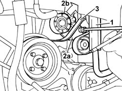
1. Move the power steering circuit pipe.
2. Turn lever (2a) clockwise to the end of its travel and raise mobile tensione (2b).
3. Remove the single engine components drive belt.
Refitting
- Ensure the tensioners turn freely and no play or binding is present.
Prevent the belt coming into contact with oil or solvents that could alter the flexibility of the rubber with a resulting loss of adhesion. Also check that the belt shows no signs of cracks or cuts or else it will have to be replaced.
- Positiont the drive belt, beginning from the crankshaft pulley (1) and ending with mobile tensioner (2).
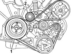
- Ensure the belt is correctly inserted in the grooves on the pulleys.
- Position the power steering circuit pipe.
Op. 4410D16 BRACKET (ONE) RETAINING CHASSIS TO BODY - R R
Op. 7055B91 RIGHT FRONT WHEEL ARCH LINER - R.R.
Op. 4450B04 RIGHT FRONT WHEEL R R
- Connect the negative battery terminal.
| Description | Connector | |
|---|---|---|
| Battery | A001B |
- Remove the vehicle from the lift.
Removing
- Position the vehicle on the lift.
Op. 4450B04 RIGHT FRONT WHEEL R R
Op. 7055B91 RIGHT FRONT WHEEL ARCH LINER - R.R.
1. The single belt tensioner is positioned as illustrated in the diagram when the belt is new, in other words when the fixed reference (1a) and the moving reference (1b) are aligned and it is possible to insert a pin in the opening (1c).
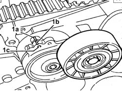
1. The single belt tensioner is positioned as illustrated in the diagram when the belt is worn, in other words when the fixed reference (1a) and the moving reference (1b) are aligned on the second moving reference.
If the single drive belt is being reused, mark the winding direction on the actual belt.
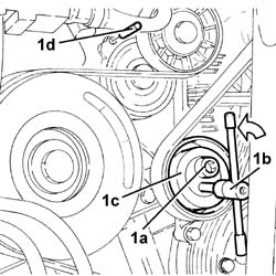
- Loosen the bolt (1a) then, using a box wrench (1b), adjust the tensioner (1c) until a 4 mm diameter pin (1d) can be fitted into the reference hole.
- Release and remove the auxiliary shaft drive belt.
Refitting
Avoid the belt coming into contact with oil or solvents that could alter the flexibility of the rubber with a resulting loss of adhesion. Also check that the belt shows no signs of cracks or cuts or else it will have to be played.
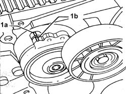
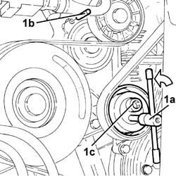
1. Fit the drive belt then, using a box wrench (1a), rotate the tensioner until it is possible to release the 4 mm diameter pin (1b) from the reference opening, then tighten the bolt (1c) to torque.
| Value - daNm | Fastening | Component | Ø | |
|---|---|---|---|---|
| 4,5 | Bolt | VARIOUS S D BELT CAM TENSIONER |
- If the same belt is being fitted and not a replacement belt, carry out the procedure described below.
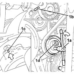
1. Using a box wrench (1a), rotate the tensioner until the pin (1b) can be released; still using the box wrench, tension the belt until the references in the wear indicator (1c) are aligned, then tighten the bolt (1d) to torque.
Op. 7055B91 RIGHT FRONT WHEEL ARCH LINER - R.R.
Op. 4450B04 RIGHT FRONT WHEEL R R
- Remove the vehicle from the lift.
Removing
- Position the vehicle on the lift.
Op. 4450B04 RIGHT FRONT WHEEL R R
Op. 7055B91 RIGHT FRONT WHEEL ARCH LINER - R.R.
1. The single belt tensioner is positioned as illustrated in the diagram when the belt is new, in other words when the fixed reference (1a) and the moving reference (1b) are aligned and it is possible to insert a pin in the opening (1c).
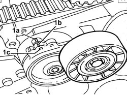
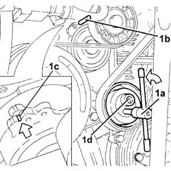
1. The single belt tensioner is positioned as illustrated in the diagram when the belt is worn, in other words when the fixed reference (1a) and the moving reference (1b) are aligned on the second moving reference.
If the single drive belt is being reused, mark the winding direction on the actual belt.
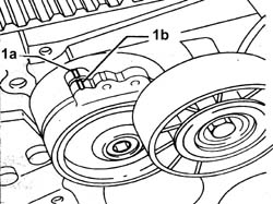
1. Loosen the bolt (1a), then use a box wrench (1b) to adjust the tensioner (1c) until a 4 mm diameter pin (1d) can be fitted into the reference hole.
- Release and remove the auxiliary shaft drive belt.
Refitting
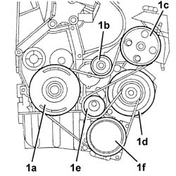
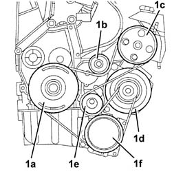
1. Fit the single drive belt following the order illustrated; (1a) crankshaft pulley, (1b) tensioner with wear indicator, (1c) power assisted steering pump, (1d) alternator, (1e) cam tensioner, (1f) compressor.
Avoid the belt coming into contact with oil or solvents that could alter the flexibility of the rubber with a resulting loss of adhesion. Also check that the belt shows no signs of cracks or cuts or else it will have to be played.
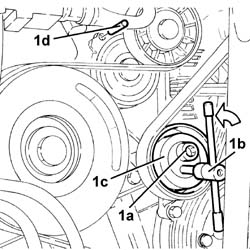
1. Fit the drive belt then, using a box wrench (1a), rotate the tensioner until it is possible to release the 4 mm diameter pin (1b) from the reference opening, then tighten the bolt (1c) to torque.
| Value - daNm | Fastening | Component | Ø | |
|---|---|---|---|---|
| 1b | 4,5 | Bolt | VARIOUS S D BELT CAM TENSIONER |
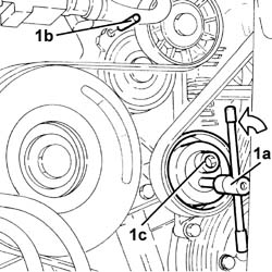
- If the same belt is being fitted and not a replacement belt, carry out the procedure described below.
1. Using a box wrench (1a), rotate the tensioner until the pin (1b) can be released; still using the box wrench, tension the belt until the references in the wear indicator (1c) are aligned, then tighten the bolt (1d) to torque.
Op. 7055B91 RIGHT FRONT WHEEL ARCH LINER - R.R.
Op. 4450B04 RIGHT FRONT WHEEL R R
- Remove the vehicle from the lift.
Removing
Op. 4450B04 RIGHT FRONT WHEEL R R
Op. 7055B91 RIGHT FRONT WHEEL ARCH LINER - R.R.
Op. 4410D16 BRACKET (ONE) RETAINING CHASSIS TO BODY - R R
- < R1 > [Right side, front]
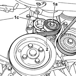
1. Adjust the moving tensioner bolt (1a) and turn it in an anti-clockwise direction to align the moving reference (1b) with the fixed reference (1c) and fit the pin.
2. Remove the auxiliary shaft drive belt.
Refitting
- Fit the belt on the various components.
Avoid the belt coming into contact with oil or solvents that could alter the flexibility of the rubber with a resulting loss of adhesion. Also check that the belt shows no signs of cracks or cuts or else it will have to be played.
- Remove the pin so that the moving tensioner tensions the belt.
Op. 4410D16 BRACKET (ONE) RETAINING CHASSIS TO BODY - R R
- < R1 > [Right side, front]
Parts & tools for this job Staging For 2002 Fiat Ulysse
- PARTEngine gasket setSearch: Fiat Ulysse 2002 engine gasket set
- TOOLTorque wrenchSearch: 3/8 inch torque wrench
- TOOLFeeler gauge setSearch: feeler gauge set
Links open Amazon search results in a new tab. As an Amazon Associate I earn from qualifying purchases.