
Alternator - r+r
- Make
- Alfa Romeo
- Model
- GT Factory Service Manual
- Year
- 2003–2010
- Section
- Current generator › Alternator - r+r
ALTERNATOR - R+R
Removing
Position the vehicle on a lift.
Make sure that the ignition key is in the OFF position, then disconnect the negative battery terminal (-)
| Description | Connector | |
|---|---|---|
| Battery | See A1B BATTERY ( BATTERY NEGATIVE ) |
Proceed with the removal
Op. 1016A40 IGNITION COIL COVER ON CYLINDER HEAD- R+R.
Proceed with the removal
Op. 7055B54 UNDER-ENGINE GUARD - R R.
Proceed with the removal
Op. 1076B18 RIGID SECTION OF EXHAUST PIPE BETWEEN CATALYTIC CONVERTER AND SILENCER - R + R.
Proceed with the removal
Op. 5520B10 STARTER MOTOR - R+R.
Proceed with the removal
Op. 1048A59 PIPE from flow meter to throttle casing hose - R.R..
Proceed with the removal
Proceed with the removal
Op. 5530B52 BATTERY DRIP TRAY/SUPPORT - R.R..
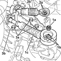
1. Remove retainer (1a), press clips (1b) and disconnect the gear engagement cable (1c).
2. Press the clips (2a) and disconnect the gear selector cable (2b).
3. Unscrew bolts (3a) and move aside bracket (3b) complete with gear selection and engagement cables.
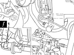
1. Disconnect the electrical connection from the fuel vapour recovery solenoid valve.
| Description | Connector | |
|---|---|---|
| 1 | Fuel vapour recovery solenoid valve | See L10 FUEL VAPOUR RECOVERY SOLENOID |
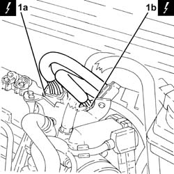
1. Disconnect the engine wiring electrical connections (1a) and (1b) and move aside.
| Description | Connector | |
|---|---|---|
| 1a | Front/engine coupling | See D4A FRONT/ENGINE CONNECTION ( CONNECTORS ) |
| Description | Connector | |
|---|---|---|
| 1b | Front/engine coupling | See D4B FRONT/ENGINE CONNECTION ( CONNECTORS ) |
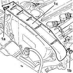
1. Undo bolts (1a), nut (1b) and remove the auxiliary drivebelt protection (1c).
Proceed with the removal
Op. 4450B04 RIGHT FRONT WHEEL R R.
Proceed with the removal
Op. 7055B66 ENGINE COMPARTMENT DUST SHIELD PROTECTION IN RIGHT FRONT WHEEL ARCH - R.R..
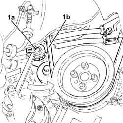
1. Adjust the mobile tensioner (1a) with a wrench and remove the auxiliary drivebelt (1b).
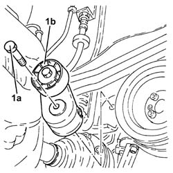
1. Undo the bolt (1a) and remove the engine components single belt moving tensioner (1b).
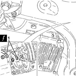
1. Disconnect the electrical connections from the alternator.
| Description | Connector | |
|---|---|---|
| 1 | Alternator | See A10 ALTERNATOR |
1. Unscrew the bolts securing the rear alternator bracket.
2. Undo the bolts fixing the alternator.
3. Recover the alternator rear mounting bracket.
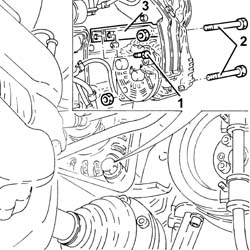
1. Remove the alternator.
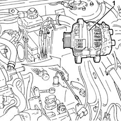
Refitting
Place the alternator and its rear mounting bracket in the housing.
Screw in the allternator fixing bolts without tightening them.
Tighten the bolts securing the rear alternator bracket.
Tighten the alternator fixing bolts to the recommended torque.
| Fastening | Component | Ø | Value (daNm) |
|---|
| Fastening | Component | Ø | Value (daNm) |
|---|
Connect the electrical connections to the alternator.
1. Position the engine components single belt moving tensioner (1a) in its housing and secure it tightening the bolt (1b) to the recommended torque.
| Fastening | Component | Ø | Value (daNm) | |
|---|---|---|---|---|
| 1b |
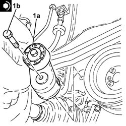
Use a wrench to turn the mobile tensioner anticlockwise and fit the auxiliary drivebelt (1b).
Proceed with the refitting
Op. 7055B66 ENGINE COMPARTMENT DUST SHIELD PROTECTION IN RIGHT FRONT WHEEL ARCH - R.R..
Proceed with the refitting
Op. 4450B04 RIGHT FRONT WHEEL R R.
Refit the auxiliary drivebelt protection in its seat and secure with the nut and bolts.
Refit the electrical wiring and connect the engine wiring electrical connections.
Connect the electrical connection to the fuel vapour recovery solenoid valve.
Refit the bracket with gear selection and engagement cables and secure with bolts.
Connect the gear selector cable.
Connect the gear engagement cable and secure with the retainer.
Proceed with the refitting
Op. 5530B52 BATTERY DRIP TRAY/SUPPORT - R.R..
Proceed with the refitting
Proceed with the refitting
Op. 1048A59 PIPE from flow meter to throttle casing hose - R.R..
Proceed with the refitting
Op. 5520B10 STARTER MOTOR - R+R.
Proceed with the refitting
Op. 1076B18 RIGID SECTION OF EXHAUST PIPE BETWEEN CATALYTIC CONVERTER AND SILENCER - R + R.
Proceed with the refitting
Op. 7055B54 UNDER-ENGINE GUARD - R R.
Proceed with the refitting
Op. 1016A40 IGNITION COIL COVER ON CYLINDER HEAD- R+R.
Connect the negative battery terminal (-).
Remove the vehicle from the lift.
Removing
Position the vehicle on a lift.
Make sure that the ignition key is in the OFF position, then disconnect the negative battery terminal (-)
| Description | Connector | |
|---|---|---|
| Battery | See A1B BATTERY ( BATTERY NEGATIVE ) |
Drain the air conditioning refrigerant circuit
Op. 0010T84 COOLANT FOR AIR CONDITIONING SYSTEM DEHYDRATE AND RECHARGE.
Proceed with the removal
Op. 4450B04 RIGHT FRONT WHEEL R R.
Proceed with the removal
Op. 7055B54 UNDER-ENGINE GUARD - R R.
Proceed with the removal
Op. 7055B64 LH OR RH REFLECTOR(ONE) ON REAR BUMPERS - R R.
Proceed with the removal
Op. 1092G10 SINGLE ENGINE BELT R R.
Proceed with the removal
Op. 7055B42 LH OR RH REFLECTOR(ONE) ON REAR BUMPERS - R R.
Proceed with the removal
Op. 7210E10 R.R. FRONT BUMPER.
Proceed with the removal
Op. 5540B76 FRONT LIGHT CLUSTER WITH FOGLAMP ONE LH OR RH R R WITH INTERFERING PARTS REMOVED
(Right and left sides).
Proceed with the removal
Op. 7025A34 BONNET LID LOCK (ONE) - R+R OR REPAIR.
Proceed with removal - 7210A15 R&R FRONT WING/HEADLAMP HOUSING CROSSMEMBER
Proceed with the removal
Op. 1076B82 LEFT EXHASUST PIPE BETWEEN CATALYTIC PRECONVERTER AND CONVERTER R R.
Proceed with the removal
Op. 1076B84 RIGHT EXHAUST PIPE BETWEEN CARALYTIC PRECONVERTER AND CONVERTER R R.
Proceed with the removal
Op. 1080B39 RIGHT CATALYTIC PRECONVERTER R R OR REPLACE CYLINDER HEAD GASKET.
Proceed with the removal
Op. 4410A80 DAMPER LOWER FORK - R R.
Proceed with the removal
Op. 2710A31 INTERMEDIATE DRIVE SHAFT - R R.
1. Disconnect the electrical connections from the alternator.
| Description | Connector | |
|---|---|---|
| 1 | Alternator | See A10 ALTERNATOR |
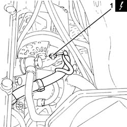
1. Undo the lower alternator fixing bolt.
2. Loosen the upper bolt fixing the alternator.
Turn the alternator upward and lock in this position with the upper bolt.
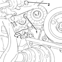
1. Undo the bolt fixing the rear alternator mounting to the crankcase.
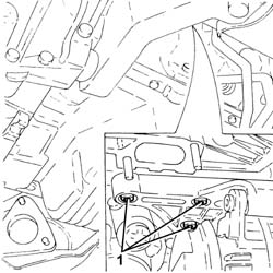
1. Unscrew the bolt securing the right rear timing belt cover to the alternator spacer.
2. Undo the lower bolt fixing the alternator mount spacer bracket to the crankcase.
3. Undo the upper bolt securing the alternator mount spacer bracket to the right cylinder head.
4. Loosen the upper bolt fixing the alternator.
5. Remove the rear alternator mounting.
6. Remove the alternator spacer.
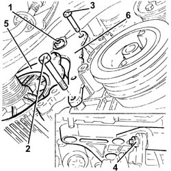
1. Working in the engine compartment, remove the alternator
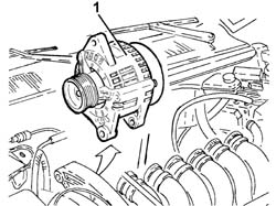
Refitting
Place the alternator in its housing.
Assemble the spacer and the rear mount to the alternator and secure with the upper bolt, keeping the alternator turned upward.
Tighten the bolts securing the alternator spacer bracket.
Tighten the bolt securing the right rear timing belt cover to the alternator spacer.
Tighten the bolt fixing the rear alternator mounting to the crankcase.
Turn the alternator in its place and secure by tightening the bolts to the specified torque.
| Fastening | Component | Ø | Value (daNm) | |
|---|---|---|---|---|
| Bolt | ALTERNATOR ASSEMBLY | M8 | (Mount side) 2.3 - 2.8 |
Connect the electrical connections to the alternator.
Proceed with the refitting
Op. 2710A31 INTERMEDIATE DRIVE SHAFT - R R.
Proceed with the refitting
Op. 4410A80 DAMPER LOWER FORK - R R.
Proceed with the refitting
Op. 1080B39 RIGHT CATALYTIC PRECONVERTER R R OR REPLACE CYLINDER HEAD GASKET.
Proceed with the refitting
Op. 1076B84 RIGHT EXHAUST PIPE BETWEEN CARALYTIC PRECONVERTER AND CONVERTER R R.
Proceed with the refitting
Op. 1076B82 LEFT EXHASUST PIPE BETWEEN CATALYTIC PRECONVERTER AND CONVERTER R R.
Proceed with refitting - 7210A15 R&R FRONT WING/HEADLAMP HOUSING CROSSMEMBER
Proceed with the refitting
Op. 7025A34 BONNET LID LOCK (ONE) - R+R OR REPAIR.
Proceed with the refitting
Op. 5540B76 FRONT LIGHT CLUSTER WITH FOGLAMP ONE LH OR RH R R WITH INTERFERING PARTS REMOVED
(Right and left sides).
Proceed with the refitting
Op. 7210E10 R.R. FRONT BUMPER.
Proceed with the refitting
Op. 7055B42 LH OR RH REFLECTOR(ONE) ON REAR BUMPERS - R R.
Proceed with the refitting
Op. 1092G10 SINGLE ENGINE BELT R R.
Proceed with the refitting
Op. 7055B64 LH OR RH REFLECTOR(ONE) ON REAR BUMPERS - R R.
Proceed with the refitting
Op. 7055B54 UNDER-ENGINE GUARD - R R.
Proceed with the refitting
Op. 4450B04 RIGHT FRONT WHEEL R R.
Refill the air conditioning refrigerant circuit
Op. 0010T84 COOLANT FOR AIR CONDITIONING SYSTEM DEHYDRATE AND RECHARGE.
Connect the negative battery terminal (-).
Remove the vehicle from the lift.
Removing
Position the vehicle on a lift.
Make sure that the ignition key is in the OFF position, then disconnect the negative battery terminal (-)
| Description | Connector | |
|---|---|---|
| Battery | See A1B BATTERY ( BATTERY NEGATIVE ) |
Proceed with removal - 1016A10 SOUNDPROOFING COVER - R&R.
Proceed with the removal
Op. 4450B04 RIGHT FRONT WHEEL R R.
Proceed with the removal
Op. 7055B54 UNDER-ENGINE GUARD - R R.
Proceed with the removal
Op. 7055B91 RIGHT FRONT WHEEL ARCH LINER - R.R..
Proceed with the removal
Op. 1092G10 SINGLE ENGINE BELT R R.
Proceed with the removal
Op. 1044B10 FUEL FILTER ASSEMBLY - R + R OR REPLACE.
Proceed with the removal
Op. 1080D34 ENGINE OIL VAPOUR SEPARATOR - R + R.
Proceed with the removal
Op. 1084A16 OIL DIP STICK PIPE - R R.
1. Disconnect the electrical connections from the alternator.
| Description | Connector | |
|---|---|---|
| 1 | Alternator | See A10 ALTERNATOR |
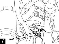
1. Undo the bolts (1a) and remove the power steering pump protection (1b).
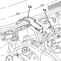
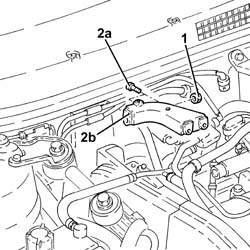
1. Loosen the upper bolt fixing the alternator.
2. Undo the bolts (2a) and remove the alternator rear mounting bracket (2b).
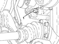
1. Undo the lower alternator fixing bolt.
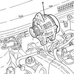
1. Remove the alternator.
Refitting
Place the alternator in its housing and secure it provisionally using the lower bolt.
Place the rear alternator bracket in its housing and secure it using the bolts.
Tighten both alternator fixing bolts to the recommended torque.
| Fastening | Component | Ø | Value (daNm) | |
|---|---|---|---|---|
| Bolt | ALTERNATOR ASSEMBLY | M10 | 4.5 ÷ 5.5 |
| Fastening | Component | Ø | Value (daNm) | |
|---|---|---|---|---|
| Upper bolt | ALTERNATOR ASSEMBLY | M12 | 6.3 ÷ 7.7 |
Place the power steering pump protection in its housing and secure it using the bolts.
Connect the electrical connections to the alternator.
Proceed with the refitting
Op. 1084A16 OIL DIP STICK PIPE - R R.
Proceed with the refitting
Op. 1080D34 ENGINE OIL VAPOUR SEPARATOR - R + R.
Proceed with the refitting
Op. 1044B10 FUEL FILTER ASSEMBLY - R + R OR REPLACE.
Proceed with the refitting
Op. 1092G10 SINGLE ENGINE BELT R R.
Proceed with the refitting
Op. 7055B91 RIGHT FRONT WHEEL ARCH LINER - R.R..
Proceed with the refitting
Op. 7055B54 UNDER-ENGINE GUARD - R R.
Proceed with the refitting
Op. 4450B04 RIGHT FRONT WHEEL R R.
Proceed with refitting - 1016A10 SOUNDPROOFING COVER - R&R.
Connect the negative battery terminal (-).
Remove the vehicle from the lift.
Removing
- Position the vehicle on a lift.
- Make sure that the ignition key is in the OFF position, then disconnect the battery terminal (-).
- Op. 1016A40 IGNITION COIL COVER ON CYLINDER HEAD- R+R
- Op. 1072C44 EXHAUST MANIFOLD HEAT SHIELD ON BULKHEAD - R+R
- Op. 1080B40 CATALYTIC PRE-CONVERTER - R R
- Op. 5520B10 STARTER MOTOR - R+R
- Op. 5530B10 BATTERY - R+R
- Op. 5530B52 BATTERY DRIP TRAY/SUPPORT - R.R.
- Disconnect the gear selector and engagement cables.
To disconnect the gear selection cable, press the release tabs shown in the figure and withdraw the cable.
2. Remove the retaining plates (2a) and release the gear selector and engagement cables rom the mounting bracket (2b).
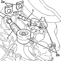
- Disconnect the electrical connection from the fuel vapour recovery solenoid valve.
| Description | Connector | |
|---|---|---|
| 1 | FUEL VAPOUR RECOVERY SOLENOID | See L10 FUEL VAPOUR RECOVERY SOLENOID |
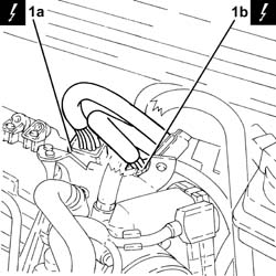
- Disconnect the engine wiring electrical connections (1a) and (1b) and move aside.
| Description | Connector | |
|---|---|---|
| 1a | Front/engine coupling | See D4 FRONT/ENGINE JUNCTION |
| Description | Connector | |
|---|---|---|
| 1b | Front/engine coupling | See D4 FRONT/ENGINE JUNCTION |
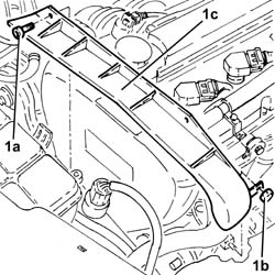
- Undo bolts (1a), nut (1b) and remove the auxiliary drivebelt protection (1c).
- Op. 4450B04 RIGHT FRONT WHEEL R R
- Op. 7055B66 ENGINE COMPARTMENT DUST SHIELD PROTECTION IN RIGHT FRONT WHEEL ARCH - R.R.
- Adjust the mobile tensioner (1a) with a wrench and remove the auxiliary drivebelt (1b).
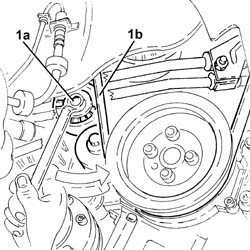
- Undo the bolt (1a) and remove the engine components single belt moving tensioner (1b).
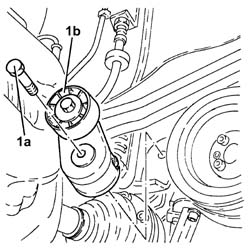
- Disconnect the electrical connections from the alternator.
| Description | Connector | |
|---|---|---|
| 1 | ALTERNATOR | See A10 ALTERNATOR |
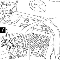
- Unscrew the bolts securing the rear alternator bracket.
- Undo the bolts fixing the alternator.
- Recover the alternator rear mounting bracket.
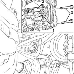
- Remove the alternator.
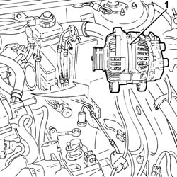
Refitting
- Place the alternator and its rear mounting bracket in the housing.
- Screw in the allternator fixing bolts without tightening them.
- Tighten the bolts securing the rear alternator bracket.
- Tighten the alternator fixing bolts to the recommended torque.
| Fastening | Component | Ø | Value (daNm) | |
|---|---|---|---|---|
| Bolt | ALTERNATOR ASSEMBLY |
- Connect the electrical connections to the alternator.
- Position the engine components single belt moving tensioner (1a) in its housing and secure it tightening the bolt (1b) to the recommended torque.
| Fastening | Component | Ø | Value (daNm) | |
|---|---|---|---|---|
| Bolt | SINGLE BELT MOVING TENSIONER VARIOUS |
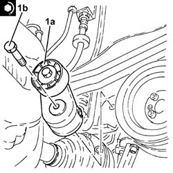
- Use a wrench to turn the mobile tensioner anticlockwise and fit the auxiliary drivebelt (1b).
- Op. 7055B66 ENGINE COMPARTMENT DUST SHIELD PROTECTION IN RIGHT FRONT WHEEL ARCH - R.R.
- Op. 4450B04 RIGHT FRONT WHEEL R R
- Refit the auxiliary drivebelt protection in its seat and secure with the nut and bolts.
- Refit the electrical wiring and connect the engine wiring electrical connections.
- Connect the electrical connection to the fuel vapour recovery solenoid valve.
- Connect the gear selection and engagement cables and secure to the mounting bracket with the retaining plates.
- Op. 5530B52 BATTERY DRIP TRAY/SUPPORT - R.R.
- Op. 5530B10 BATTERY - R+R
- Op. 5520B10 STARTER MOTOR - R+R
- Op. 1080B40 CATALYTIC PRE-CONVERTER - R R
- Op. 1072C44 EXHAUST MANIFOLD HEAT SHIELD ON BULKHEAD - R+R
- Op. 1016A40 IGNITION COIL COVER ON CYLINDER HEAD- R+R
- Connect the negative battery terminal (-).
- Remove the vehicle from the lift.
Parts & tools for this job Staging For 2003 Alfa Romeo GT
- TOOLBattery testerSearch: car battery tester
- TOOLDigital multimeterSearch: automotive digital multimeter
- TOOLBattery terminal cleanerSearch: battery terminal cleaner
Links open Amazon search results in a new tab. As an Amazon Associate I earn from qualifying purchases.