
E7015 Alarms (RH drive adaptation)
- Make
- Alfa Romeo
- Model
- 156 Factory Service Manual
- Year
- 1997–2002
- Section
- Car electronic systems › E7015 Alarms (RH drive adaptation)
E7015 Alarms (RH drive adaptation)
Description
The intruder alarm system offers volumetric and perimeter protection.
An electronic control unit monitors the following:
- status of doors, boot and bonnet via switches in the locks (perimeter control)
- the presence of a moving object inside the passenger compartment, via volumetric sensors. (volumetric control)
- the condition of the system supply cables (both directly from the battery and those controlled by the ignition)
- the condition of emergency key supply leads
- the operation of ignition switch
The control unit is equipped with an autodiagnostic function which detects and memorizes faults in the control unit itself and the system components and also checks the condition of the connecting cables.
The control unit also memorizes the number of times the alarm is activated and set off.
The control unit operating software may be altered to meet regulations governing the use of alarm systems applicable in different markets.
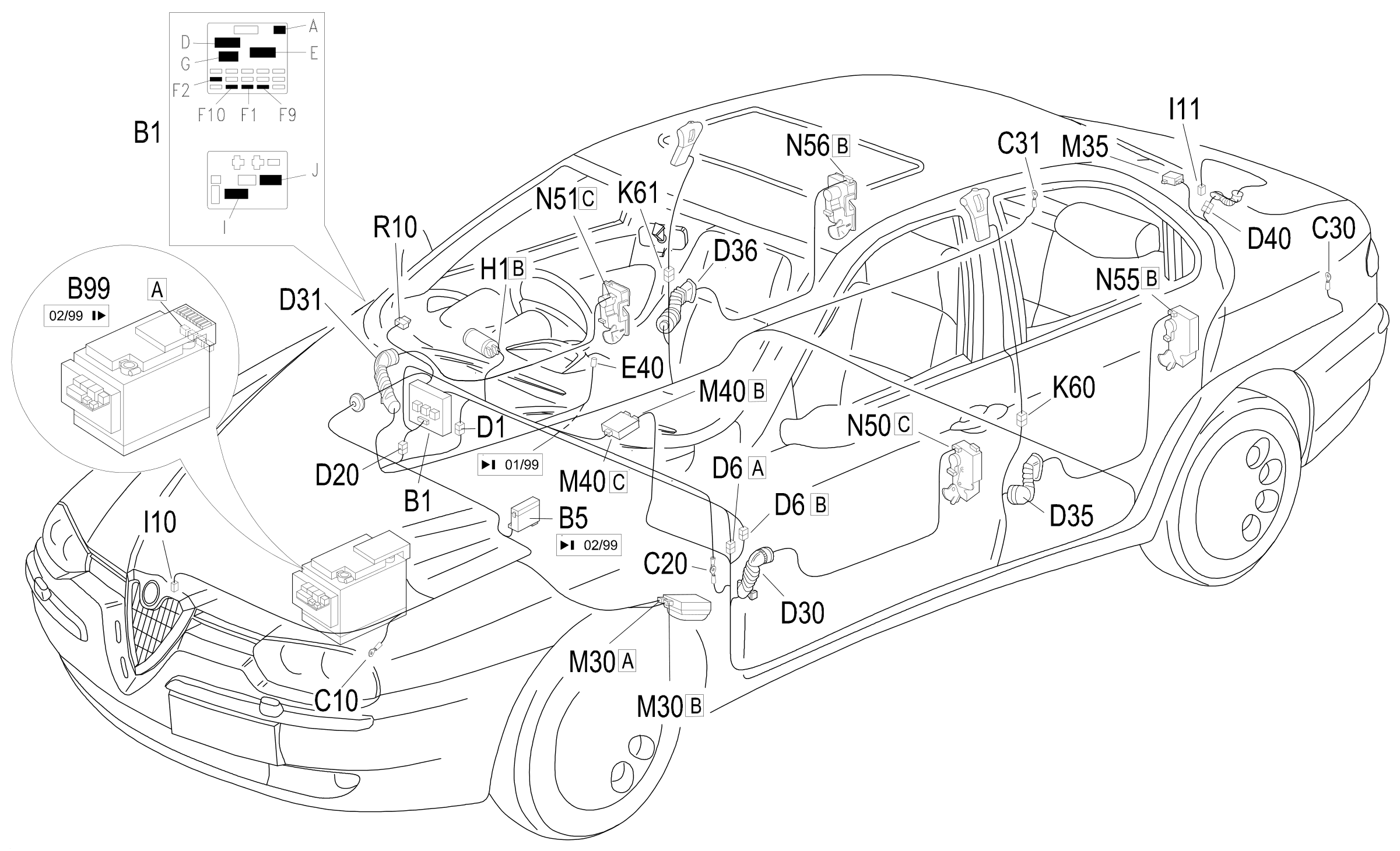
The electronic control unit, which also incorporates the siren, is located at the front, under the wheel arch to the left of the engine compartment.
The receiver is an electronic device which receives the transmitter signal. It is located in the rear part of the roof panel.
It is connected to the control unit via the serial line and directly manages the following system functions:
- it receives, decodes and manages the remote control signals
- it locks and unlocks the doors
- it stores the codes of enabled transmitters.
The receiver also has its own autodiagnostic function which detects and memorizes faults in the receiver and the components connected to it and it checks the condition of the connecting cables.
The emergency key for deactivating the system (not available in some markets) is located on the left of the dashboard, next to the junction unit. It cuts out the system, for example in the case of repair interventions.
The door lock system switches are used to check doors, boot and bonnet. A special switch is also located on the bonnet catch.
The volumetric sensors check for car intruders. They are located in the two centre pillars. Both are twin sensors, i.e. consisting of an emitter and a receiver: the wave transmitted by an emitter should reach the receiver of the other sensor and viceversa: if this is not the case, an alarm signal is sent to the control unit.
The dissuasion LED is located in the dashboard, in the centre above the air vent and signals the state of the system (on, off, etc.) plus any faults.
For more details see DESCRIPTION AND OPERATION: 5580E Anti-theft device .
The alarm system control unit has direct supply lines and lines controlled by the ignition protected by two fuses in the junction unit., such as the remote control unit receiver.
Description of operation
The alarm system is controlled by alarm control unit M30 integral with the siren.
The control unit is supplied directly by the battery at pin 3 of connector A from the line protected by fuse F10 and at pin 7 of connector B (supply for the direction indicators) from the line protected by fuse F9; both fuses are located in junction unit B1.
The supply controlled by the ignition (INT) reaches pin 12 of connector B of control unit M30 through a line protected by fuse F1 of control unit B1.
Pin 9 of connector A is earthed.
Control unit M30 controls door closure via switches N50, N55, N51, N56, which send an earth signal to pins 8, 15, 9 and 16 of connector B respectively when the door is open (the same switches light up the timed lights: Wiring diagram E2510 ROOF LAMP ).
The bonnet lid is controlled by switch I10, which is connected to pin 18 of connector B, while the boot lid is controlled by switch I11, which is connected to pin 17 of connector B (the same switch turns on the boot light: Wiring diagram E2520 COMPARTMENT LIGHT- BOOT LIGHT - SUN SHIELD LIGHT )
Pin 1 of connector A of M30 sends alarm led control signal E40.
The left volumetric sensor (K60) and the right volumetric sensor (K61), receive a supply and earth from pins 8 and 11, respectively, of connector A of M30 and send the alarm control signal to pin 12 of connector A of M30.
Pins 1 and 2 of connector B of M30 produce control signals for turn signals ( Wiring diagram E2020 TURN/ HAZARD LIGHTS ).
The receiver for the remote control M35 is supplied directly by the battery at pin 3 from the line protected by fuse F10 and at pin 7 from the line protected by fuse F9; both fuses are located in the junction unit B1. Pin 4 is earthed.
M35 (pins 5 and 6) gives out signals directed to pins 15 (door locking signal) and 6 (door unlocking signal) for the integrated services control unit M40 ( Wiring diagram E3040 DOOR LOCKING DEVICE ).
The control unit M30 and the receiver M35 are both equipped with an autodiagnostic system which can be used by connecting to connector R10: it receives signals from pin 6 of connector A of M30 and from pin 4 of the remote control receiver M35.
This serial line also acts as a connection between M30 and M35.
Wiring diagram
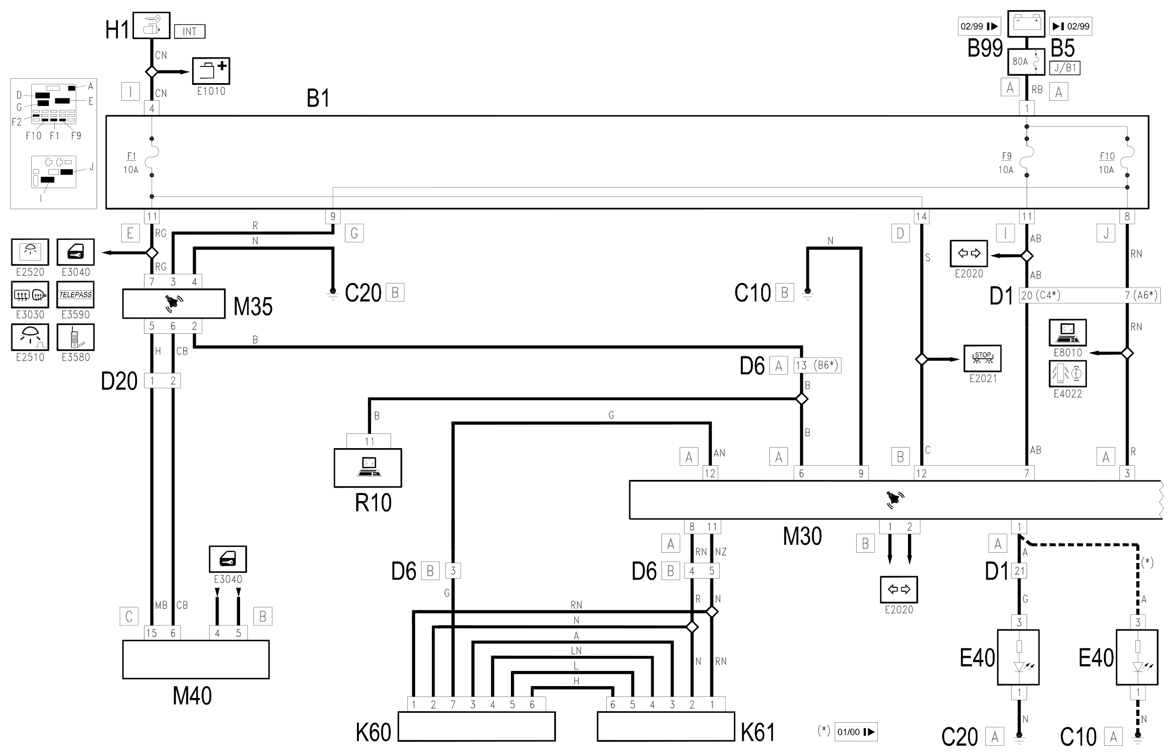
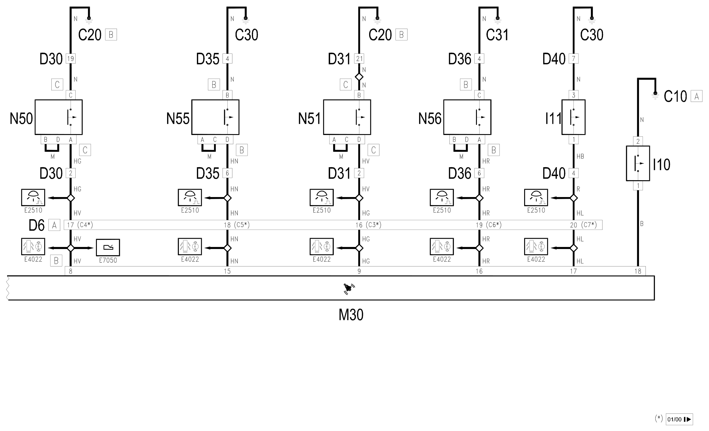
Components
| Code | Component | See |
|---|---|---|
| B01 | Junction unit | description 5505A |
| B05 | MAXI FUSE-1 box | |
| B99 | Maxifuse box on battery | |
| C10 | Front left earth | description 5505A |
| C20 | Passenger side dashboard earth | description 5505A |
| C30 | Left rear earth | description 5505A |
| C31 | Rear right earth | description 5505A |
| D01 | Front / dashboard connection | |
| D06 | Front / rear connection | |
| D20 | Dashboard/rear connection | |
| D30 | Rear / front door connection left | |
| D31 | Right front door rear coupling/. | |
| D35 | Rear/right door connection left | |
| D36 | Rear/right door connection door | |
| D40 | Rear / boot connection | |
| D87 | Left tailgate rear coupling/ | |
| E40 | Alarm LED | description 5580E |
| H01 | Ignition switch | description 5520A |
| H70 | Alarm switch | description 5580E |
| I10 | Bonnet opening switch | description 5580E |
| I11 | Boot opening switch | description 5580E |
| K60 | Left alarm volumetric sensor | description 5580E |
| K61 | Volumetric sensor for right alarm | description 5580E |
| M30 | Alarm control unit | description 5580E |
| M35 | Alarm remote control receiver | description 5580E |
| M40 | Integrated services control unit | description 5505A |
| N50 | Right front door lock left | description 7005N |
| N51 | Right front door lock motor | description 7005N |
| N55 | Rear door lock geared motor left | description 7010N |
| N56 | Rear door lock geared motor right | description 7010N |
| R10 | Multiple tester connection |
Component location
Parts & tools for this job Staging For 1997 Alfa Romeo 156
- TOOLDigital multimeterSearch: automotive digital multimeter
- PARTAssorted fuse kitSearch: car fuse assortment kit
- TOOLWire crimper and connector kitSearch: wire crimper connector kit
Links open Amazon search results in a new tab. As an Amazon Associate I earn from qualifying purchases.