
E2020 Turn/ hazard lights
- Make
- Alfa Romeo
- Model
- 156 Factory Service Manual
- Year
- 1997–2002
- Section
- Exterior lighting › E2020 Turn/ hazard lights
E2020 Turn/ hazard lights
Description
The direction indicators and hazard warning lights delimit the outer dimensions of the car.
The left and right direction indicators are operated by raising or lowering the appropriate lever on the stalk unit.
The hazard warning lights (right and left direction indicators operated simultaneously) are turned on by the pressing the red button in the centre of the dashboard.
The direction indicators work with the ignition on, while for safety reasons, the hazard warning lights can be turned on at any time, as they are supplied directly from the battery.
The circuit for the direction indicators and hazard warning lights is protected by a single fuse.
Two warning lights in the panel (rev counter module), also intermittent, signal that the left and right direction indicators are turned on.
The red hazard warning light button contains two leds: the first green one is ignition-operated and lights up the specific symbol; The second red light comes on intermittently when the hazard warning lights are operated.
The hazard warning lights are also operated by the alarm system, which is connected directly to the power supply to the lights.
Description of operation
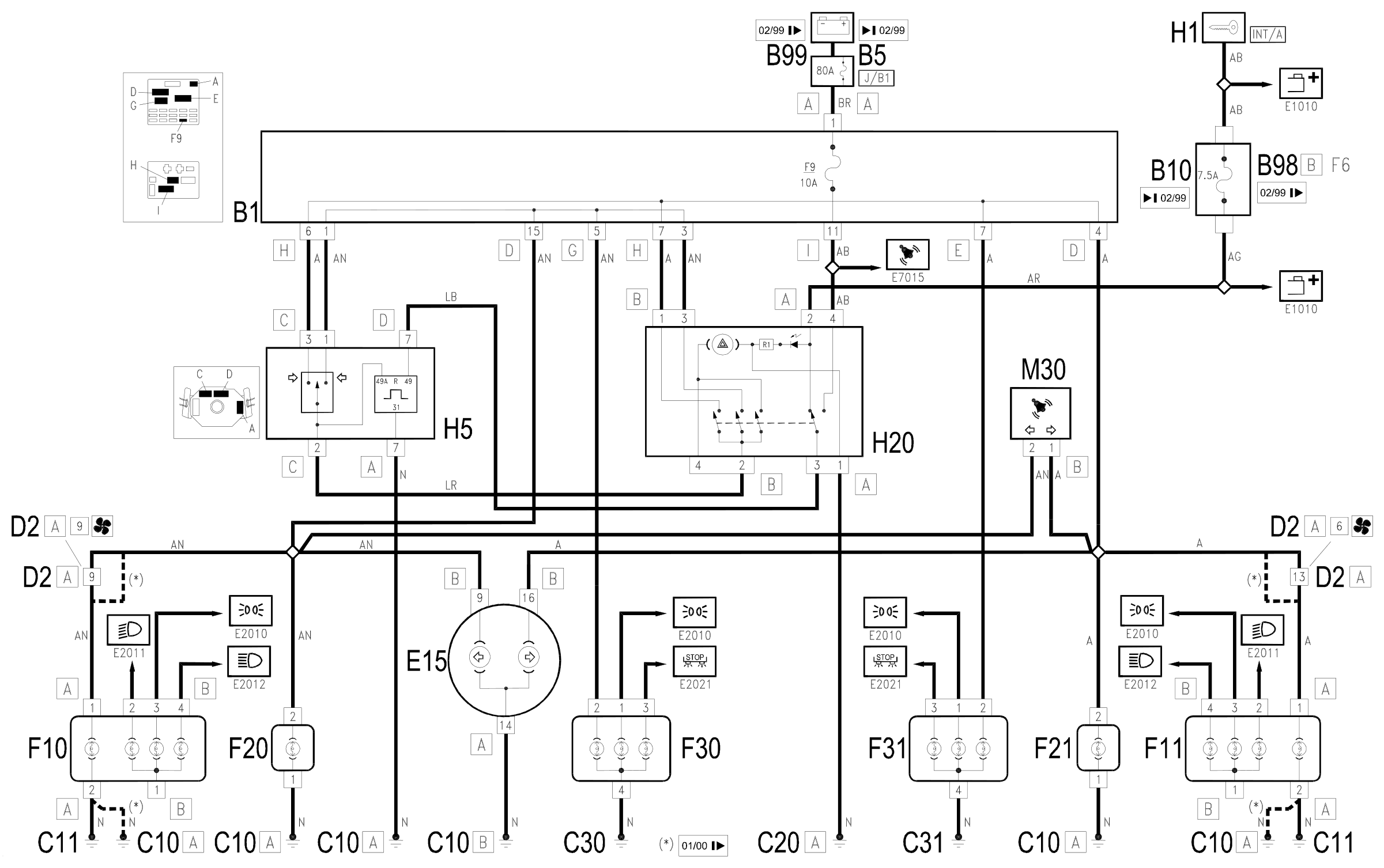
The circuit is controlled by the hazard warning lights switch H20.
The intermittent device is located on the steering column switch unit H5. It is connected to earth at pin 7 of connector A and receives a supply signal at pin 7 of connector D through switch H20:
- when the hazard lights are not off, the supply is controlled by the ignition (INT/A) through the line for fuse B10 up to 2/99 or from fuse F6 of the additional fuse box B98B from 2/99
- when the hazard lights are on, the supply is direct from the battery through fuse F9 of the junction unit B1 and maxifuse J/B1 of B5 up to 2/99 or of B99 from 2/99.
The intermittent device produces a signal which supplies the switch for the direction indicators on the steering column switch H5 and the switch H20.
The operation, in one direction or another, of the steering column switch lever H5 supplies the right direction indicators (F11, F21, F31) or the left ones (F10, F20, F30).
At the same time the warning light, located in the rev counter module E15, comes on.
Pressing the switch H20 closes three contacts which simultaneously supply all the lights (right branch and left branch) close and the red LED in the actual switch which lights up the symbol in flashing mode.
In switch H20 there is also a green LED which comes on when the ignition is switched on (INT/A).
All the hazard warning lights are also operated by the alarm system control unit M30 (pins 1 and 2 of connector B), which is connected directly to the light power supply ( Wiring diagram E7015 ALARMS ).
Wiring diagram
Components
| Code | Component | See |
|---|---|---|
| B01 | Junction unit | description 5505A |
| B05 | MAXI FUSE-1 box | |
| B10 | Key-dependent supply fuse (INT/A) | |
| B98 | Supplementary fuse box | description 5505A |
| B99 | Maxifuse box on battery | |
| C10 | Front left earth | description 5505A |
| C11 | Right front earth | description 5505A |
| C20 | Passenger side dashboard earth | description 5505A |
| C30 | Left rear earth | description 5505A |
| C31 | Rear right earth | description 5505A |
| D02 | Front /crossmember connection | |
| E15 | Rev counter | description 5560B |
| F10 | Left headlamp | description 5540B |
| F11 | Right headlamp | description 5540B |
| F20 | Left side repeater | description 5550C |
| F21 | Right side repeater | description 5550C |
| F30 | Rear lights cluster left (fixed part) | description 5540A |
| F31 | Rear right lights cluster (fixed part) | description 5540A |
| H01 | Ignition switch | description 5520A |
| H05 | Steering column switch unit | description 5550A |
| H20 | Hazard warning lights switch | description 5550C |
| J43 | Direction indicators / hazard warning lights relay | |
| M30 | Alarm control unit | description 5580E |
| M35 | Alarm remote control receiver | description 5580E |
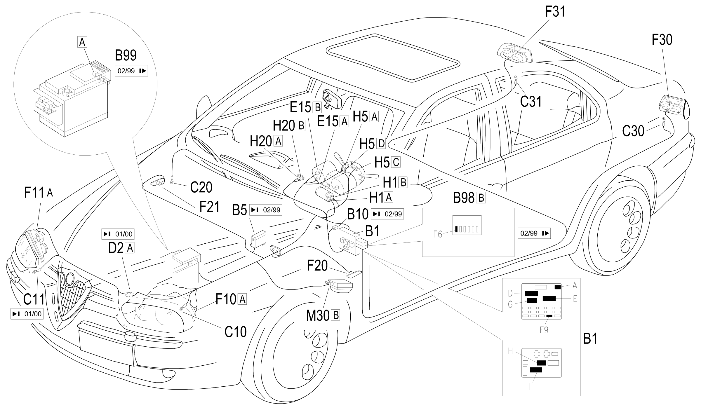
Component location
Parts & tools for this job Staging For 1997 Alfa Romeo 156
- PARTReplacement bulbsSearch: Alfa Romeo 156 1997 bulbs
- TOOLDigital multimeterSearch: automotive digital multimeter
Links open Amazon search results in a new tab. As an Amazon Associate I earn from qualifying purchases.