
E2510 Roof lamp
- Make
- Alfa Romeo
- Model
- 156 Factory Service Manual
- Year
- 1997–2002
- Section
- Interior lighting › E2510 Roof lamp
E2510 Roof lamp
Description
The front interior light includes two courtesy lights with two control switches.
With the left switch (A) it is possible to select the following two operating modes:
- centre position: both lights come on for a timed period when the doors are opened
- left-hand position: both lights are off all the time;
- right-hand position: both lights are on all the time.
The right-hand switch turns on only one of the lights:
- left-hand position: left-hand light always on;
- right-hand position: right-hand light always on;
- central position: both lights always off.
Both rear interior lights contain a courtesy light that operates in different modes according to the position of the lens, which operates an internal switch.
- neutral position: light comes on for a timed period when the doors are opened;
- positioned to one side: light always off;
- positioned to the other side: lights always on.
The courtesy light timing is controlled according to a logic managed by the integrated services control unit, on the right hand side, under the dashboard, which can be summarized as follows.
When any of the four doors is opened, all front and rear courtesy lights are operated for a timed period.
- timed period of 7 seconds when the locks are unlocked using the key or the remote control;
- timed period of 7 seconds when a previously opened door is reclosed; timing is suspended when the key is turned to MAR (this function allows the driver to enter the car and insert the key in the ignition)
- timed interval of 3 minutes if one of the doors is left open (this function prevents the battery going flat if the car is left with a door open)
When one of the other doors is opened, the current timer count is reset to zero.
The courtesy light circuit is protected by a special junction unit fuse. two fuses also protect the integrated services control unit direct and ignition-operated supply lines.
Description of operation
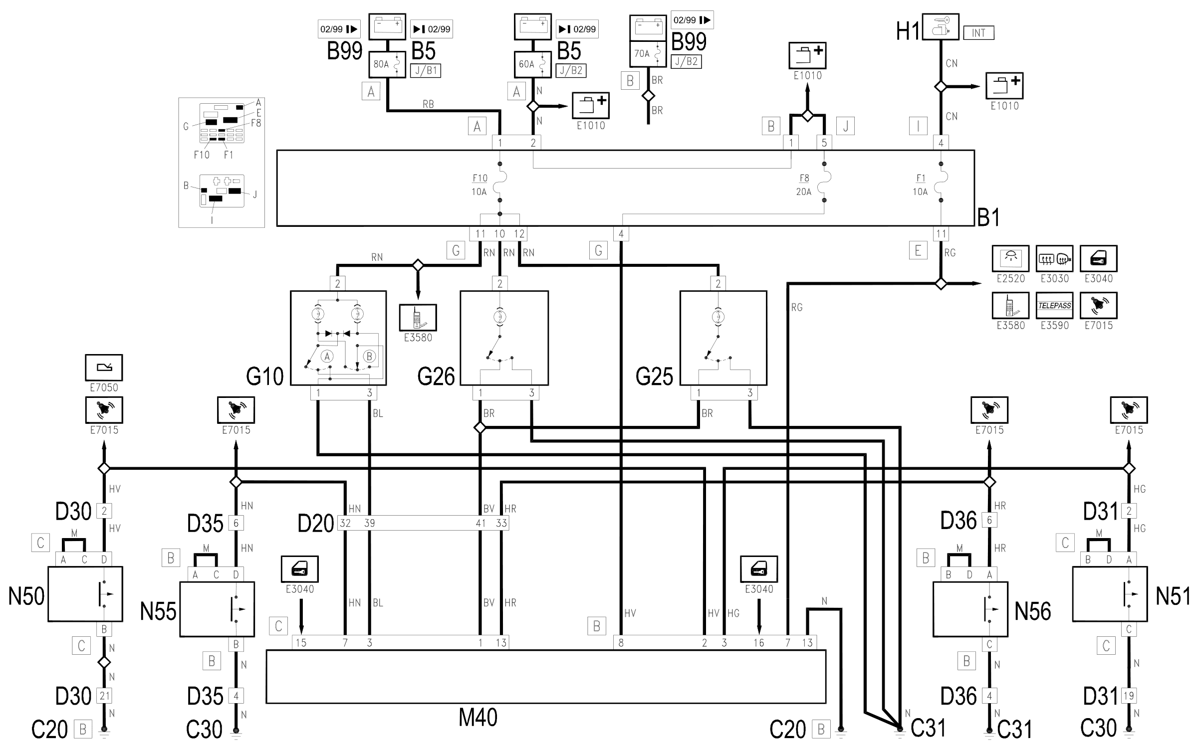
The supply for the front (G10) and rear (G25 and G26)courtesy lights arrives directly from the battery. (maxifuse J/B1 of B5 up to 2/99 or of B99 from 2/99 ) through fuse F10 of the junction unit B1.
They are switched on via a direct earth signal (permanently activated) or a signal coming from the integrated services control unit M40.
The supply for the control unit M40 is controlled by the ignition (INT) by the line for fuse F1 of the junction unit B1 (pin 7 of connector B) and directly from the battery. (maxifuse J/B2 of B5 up to 2/99 or of B99 from 2/99) through fuse F8 of the junction unit B1 (pin 8 of connector B).
The control unit sends a timed signal according to the door unlocking and door open signals which arrive:
- at pin 15 of connector C: release from the receiver for the remote control M35 Wiring diagram E3040 DOOR LOCKING DEVICE .)
- at pin 16 of connector B: unlocking of the lock of one of the front doors N50 and N51 Wiring diagram E3040 DOOR LOCKING DEVICE .)
- at pins 2 and 3 of connector B: opening of one of the front doors N50 and N51 (left and right respectively);
- at pins 7 and 13 of connector C: opening of one of the rear doors N55 and N56 (left and right respectively);
Timed earth signals which operate the front and rear courtesy lights leave pins 1 and 3 of connector C of the control unit M40 .
Wiring diagram
Components
| Code | Component | See |
|---|---|---|
| B01 | Junction unit | description 5505A |
| B05 | MAXI FUSE-1 box | |
| B99 | Maxifuse box on battery | |
| C20 | Passenger side dashboard earth | description 5505A |
| C30 | Left rear earth | description 5505A |
| C31 | Rear right earth | description 5505A |
| D20 | Dashboard/rear connection | |
| D30 | Rear / front door connection left | |
| D31 | Right front door rear coupling/. | |
| D35 | Rear/right door connection left | |
| D36 | Rear/right door connection door | |
| G10 | Front courtesy light | description 7040E |
| G20 | Rear (centre courtesy light) | description 7040E |
| G20 | Rear (centre) courtesy light | description 7040E |
| G25 | Rear left courtesy light | description 7040E |
| G26 | Rear right courtesy light | description 7040E |
| M40 | Integrated services control unit | description 5505A |
| N50 | Right front door lock left | description 7005N |
| N51 | Right front door lock motor | description 7005N |
| N55 | Rear door lock geared motor left | description 7010N |
| N56 | Rear door lock geared motor right | description 7010N |
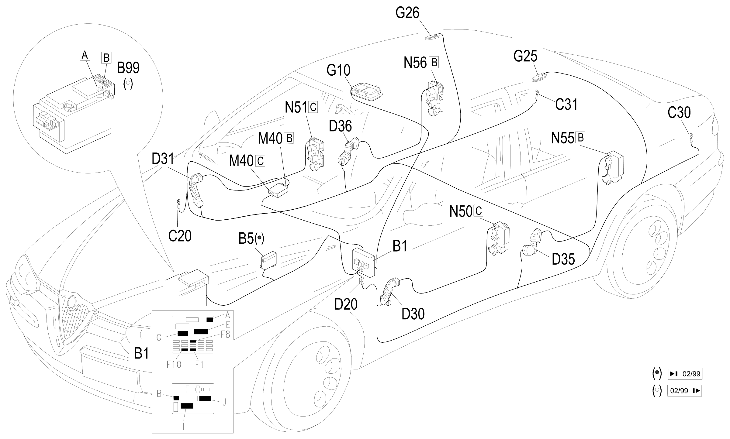
Component location
Parts & tools for this job Staging For 1997 Alfa Romeo 156
- PARTReplacement bulbsSearch: Alfa Romeo 156 1997 bulbs
- TOOLDigital multimeterSearch: automotive digital multimeter
Links open Amazon search results in a new tab. As an Amazon Associate I earn from qualifying purchases.