
E1050 Can connection lines
- Make
- Alfa Romeo
- Model
- 147 Factory Service Manual
- Year
- 2000–2002
- Section
- Power supply and ground › E1050 Can connection lines
E1050 Can connection lines
Description
This vehicle features a CAN network (Controller Area Network) system of electrical connections: it involves a software and hardware solution which is designed to manage the resources on the vehicle in an increasingly efficient way, allowing:
- data to be shared between the various electronic units;
- the integrattion of several electronic units in one network;
- a high data exchange speed in the network;
- cost-effective solutions, since the number of wiring harnesses and connectors are considerably reduced in the vehicle;
- a higher standard in terms of quality and reliability.
The advantage of using a CAN system stems from the fact that the communication involves numerous control units and consequently the number of signals managed is very high.
For this reason the signals 'travel' on CAN type (double) serial Bus, where one wire is associated with the high level (H) and the other the low level (L); These CAN Buse signals are differential, i.e. the value assigned to each bit is represented by the different voltge of CAN-H and CAN-L.
The various electronic units which make up the system, known as network 'Nodes', are connected to the CAN by means of communication interfaces known as transreceivers; These connection interfaces, integrated in the actual electronic units, form the gates for sending/reading information at the CAN or at the serial lines.
A 'transmission protocol', i.e. the set of rules allowing the communication between two or more ECUs (called Nodes) by means of data or data package exchanges, is required for CAN serial line data circulation.
The main element in the network is the Body Computer.
The Body Computer node 'wakes the system up' when the ignition key is turned to the ON position (if there is a Body Computer failure, the task of waking the system up is entrusted to the instrument panel).
The Body Computer also carries out the functions of controlling the network, which makes it possible to supply information on:
- the network activity status;
- the functional failure status of the individual electronic units (nodes);
- the possible CAN failure.
The various electronic units process the various signals coming from their sensors both for their own management and for the other control units, to which they are sent via the CAN
The specific structure adopted on this vehicle consists of two CANs which connect nodes belonging to two different areas:
- C-CAN for 'dynamic control' of the vehicle (high speed): bus CAN-H and CAN-L;
- B-CAN for the management of 'bodywork functions' (low speed): bus CAN-A and CAN-B;
The two CAN communication networks are connected to one another by means of a gateway for transferring joint information, located in the Body Computer Node.
The following nodes are connected to the Body Computer via the C-CAN:
- engine management control unit;
- ABS control unit;
- 'SELESPEED' gearbox control unit;
- steering sensor unit for VDC.
The following nodes are connected to the Body Computer via the B-CAN:
- climate control system control unit;
- instrument panel;
- radio or radio phone-navigator
- control unit in driver's door.
The diagnosis of the nodes connected to the bodywork network is achieved via the CAN, whilst the vehicle dynamic control network is diagnosed using the special K lines Wiring diagram E8010 DIAGNOSTICS MULTIPLE CONNECTOR .
The system also uses 'traditional' complementary serial lines for the various connections; for example, in the connection between the Body Computer and the alarm / volumetric sensors Wiring diagram E7015 ALARMS .
The distribution of power takes place via the junction units and/or fuse boxes, connected to the control elements (relays and static actuators) in order to ensure the maximum level of electrical protection and the minimum degree of wiring complexity Wiring diagram E1010 POWER SUPPLY .
Description of operation
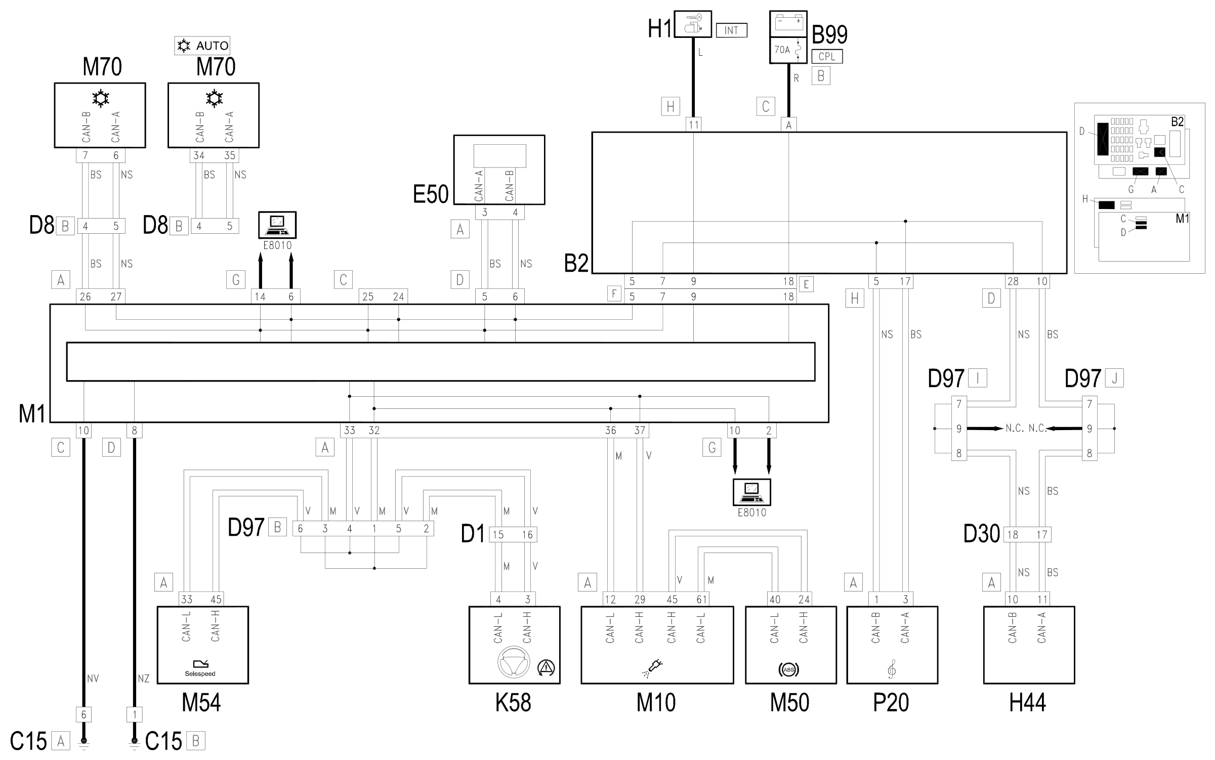
The Body Computer M1 is supplied directly by the battery from the line protected by the maxifuse CPL (B99, connector B) at pin 18 of connector F of the interface with the underdashboard control unit B2.
The Body Computer M1 receives a supply controlled by the ignition (INT) at pin 9 of connector F of the interface with the underdashboard control unit B2: this signal is designed to 'wake up the network'.
Pin 10 of connector C and pin 8 of connector D M1 are earthed.
The nodes connected to the Body Computer M1 via the C-CAN are:
- engine management control unit M10;
- ABS control unit M50 (which is not connected directly, but via M10)
- 'SELESPEED' gearbox control unit M54;
- steering sensor unit for VDC K58.
The following nodes are connected to the Body Computer M1 via B-CAN:
- climate control system control unit M70;
- instrument panel E50;
- radio or radio-phone-navigator P20;
- driver's door control unit H44.
Wiring diagram
Components
| Code | Component | See |
|---|---|---|
| B02 | Junction unit under dashboard | description 5505A |
| B99 | Maxifuse box on battery | description 5530B |
| D01 | Front / dashboard coupling | |
| D08 | /Air conditioning -heater front coupling | |
| D20 | /Rear dashboard coupling | |
| D30 | Rear coupling for /front door. driver's side | |
| D31 | /Front passenger door. rear coupling | |
| D97 | Short circuiting coupling | |
| E50 | Instrument panel | description 5560B |
| H01 | Ignition switch | description 5520A |
| H44 | Electric windows controls assembly on driver's door | description 7005M |
| K58 | Steering sensor | description 3350E |
| M01 | Body computer | description 5505A |
| M10 | Engine management ECU | description 1056B |
| M50 | ABS control unit | description 3340A |
| M54 | Selespeed transmission control unit | description 2127E |
| M70 | Climate control system control unit | description 5040D |
| P20 | Car radio |
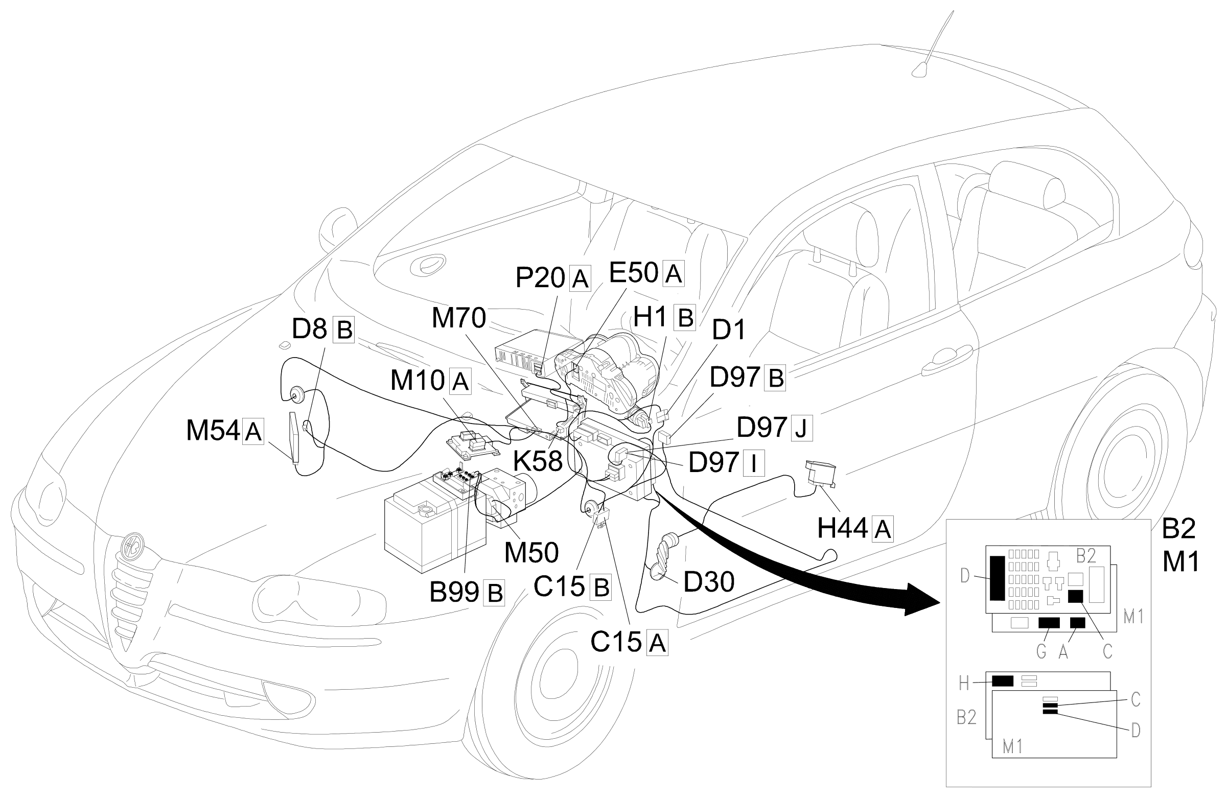
Component location
Parts & tools for this job Staging For 2000 Alfa Romeo 147
- TOOLDigital multimeterSearch: automotive digital multimeter
- PARTAssorted fuse kitSearch: car fuse assortment kit
- TOOLWire crimper and connector kitSearch: wire crimper connector kit
Links open Amazon search results in a new tab. As an Amazon Associate I earn from qualifying purchases.