
E2010 Side lights / number plate
- Make
- Alfa Romeo
- Model
- 147 Factory Service Manual
- Year
- 2000–2002
- Section
- Exterior lighting › E2010 Side lights / number plate
E2010 Side lights / number plate
Description
The side lights are switched on when the ring nut on the steering column switch unit left lever is turned to the first position.
The switching on of the side lights is managed by the Body Computer.
The function of controlling the side lights is activated by the ignition key in ON position (INT) go ahead signals and the command from the steering column switch unit: the side lights are supplied two at a time, on the left side and the right side.
Turning on the side lights also turns on the number plate lights and numerous other interior lights for passenger compartment lighting and instrument & control lighting (these lines are described and illustrated in the diagrams for the components to which they refer).
The activation and/or deactivation information is sent via the ACN: in this way the 'Side Lights' warning light in the instrument panel is also switched on.
The instrument panel also activates the serigraphy night lighting.
The 'Park' function for the side lights is switched on when the key is turned to the PARK position:
- if the direction indicators are not activated, the parking lights come on on both sides of the vehicle, like the no. plate lights and the side lights warning light;
- if the direction indicator on one side is on, the parking lights only come on on that side, whilst the no. plate lights and the side lights warning light do not come on.
The 'Follow me home' function allows the dipped headlamps and the side lights to remain on after the engine has been switched off (key in OFF and/or PARK) for a time or 30 seconds or multiples thereof.
The maintenance of the dipped headlamps is signalled by the side lights warning light in the instrument panel remaining on.
The function is switched on by operating the headlamp flasher within 2 minutes: each time the lever is operated, the time the lights remain on is increased by 30 seconds, up to a maximum of 210 secs.
Operating the headlamp flasher lever for more than 2 seconds, causes the function to be switched off; the function is also switched off if the ignition key is turned to the ON position.
The correct operation of the lights is controlled by the side lights and no. plate lights 'check' function: the following is controlled for each of the two circuits (right branch and left branch):
- open circuit or bulb missing
- short circuit to earch (bulb short circuit or wiring short circuit to earth)
- short circuit to Vbatt (wiring short circuit to Vbatt)
- 5W bulb replaced by a 21 W bulb
If one of the situations described above occurs, the Body Computer makes the failure state available to the CAN: a special 'lights failure' warning light comes on in the instrument panel and the information is shown, at the same time, on the display.
Description of operation
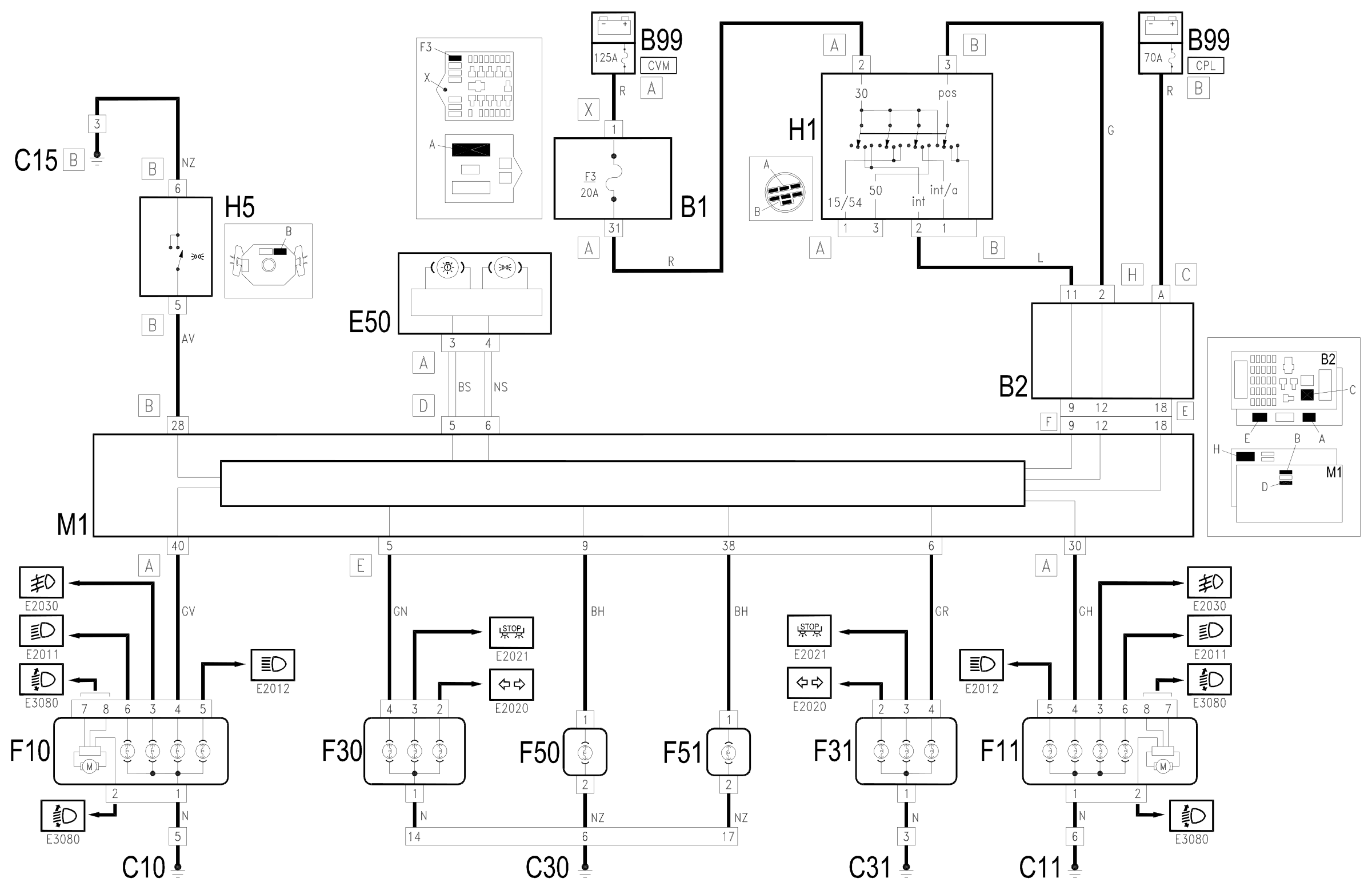
The side lights activated signal is sent to pin 28 of connector B of the Body Computer M1 from the steering column switch unit H5.
The 'key in ON' signal (INT) for the switch H1 reaches the underdashboard control unit B2, at pin 11 of connector H and from there goes to the Body Computer M1 (pin 9 of connector F).
The 'key in PARK' signal (POS) for the switch H1 reaches the underdashboard control unit B2, at pin 2 of connector H and from there goes to the Body Computer M1 (pin 12 of connector F).
The Body Computer M1 controls the supply for the front side lights F10 (left) and F11 (right) - from pins 30 and 40 of connector A, the rear side lights F30 (left) F31 (right) and the no. plate lights F50 and F51 from pins 5, 6, 9 and 38 of connector E.
The Body Computer M1 is connected via the CAN line to the instrument panel E50 to manage the 'side lights on' warning light and, if a failure is detected in the circuit, the 'lights failure' warning light.
Wiring diagram
Components
| Code | Component | See |
|---|---|---|
| B01 | Engine compartment junction unit | description 5505A |
| B02 | Junction unit under dashboard | description 5505A |
| B99 | Maxifuse box on battery | description 5530B |
| C10 | Front left earth | |
| C11 | Right front earth | |
| C15 | Facia earth, driver's side | |
| C30 | Left rear earth | |
| C31 | Rear right earth | |
| E50 | Instrument panel | description 5560B |
| F10 | Left headlamp | description 5540B |
| F11 | Right headlamp | description 5540B |
| F30 | Left. rear( light cluster on fixed part) | description 5540A |
| F31 | Right. rear light cluster (fixed part) | description 5540A |
| F50 | Left number plate light | description 5540A |
| F51 | Right number plate light | description 5540A |
| H01 | Ignition switch | description 5520A |
| H05 | Stalk unit | description 5550A |
| M01 | Body computer | description 5505A |
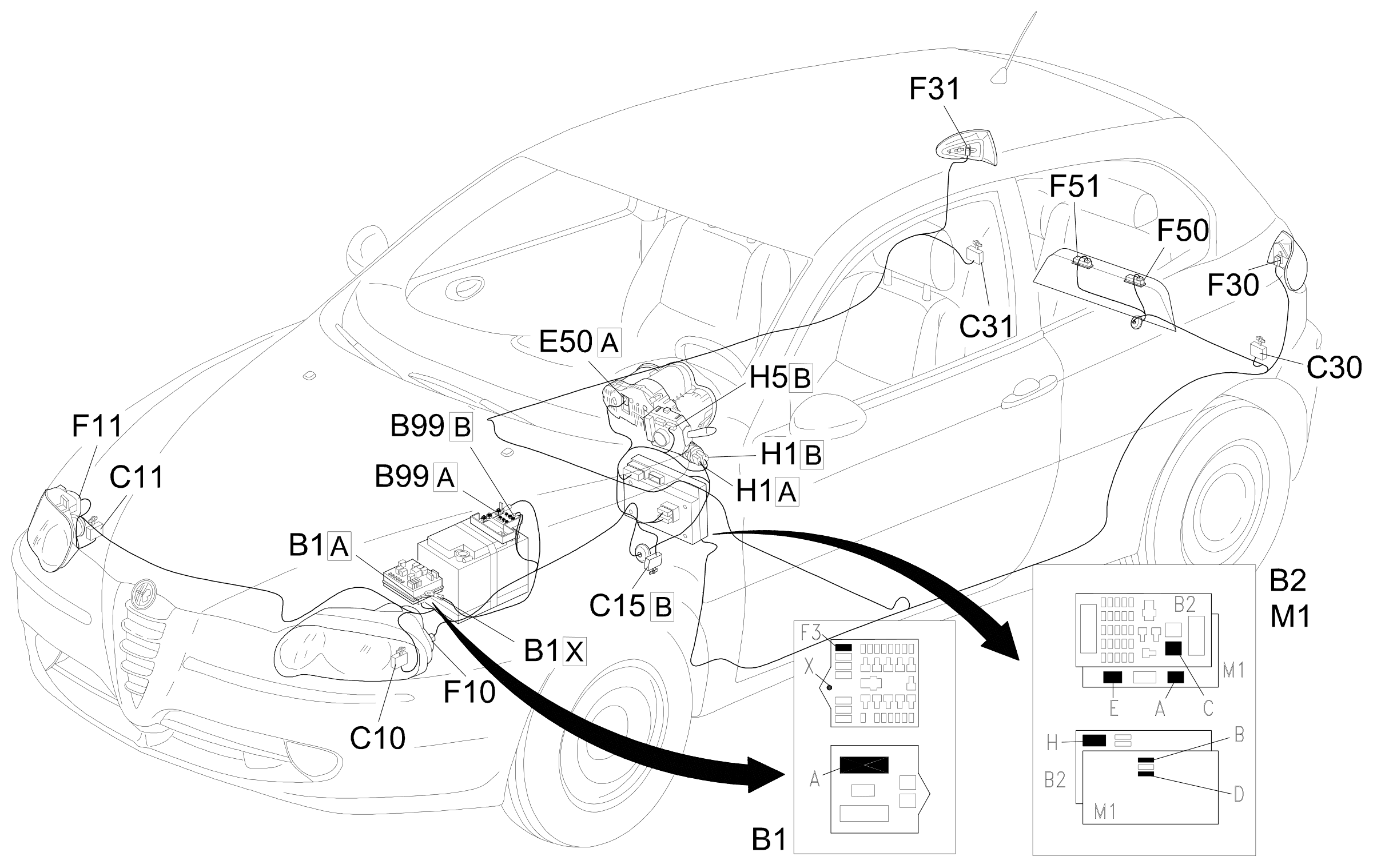
Component location
Parts & tools for this job Staging For 2000 Alfa Romeo 147
- PARTReplacement bulbsSearch: Alfa Romeo 147 2000 bulbs
- TOOLDigital multimeterSearch: automotive digital multimeter
Links open Amazon search results in a new tab. As an Amazon Associate I earn from qualifying purchases.