
BACKLIGHT GLASS (page 2 of 2)
- Make
- Land Rover
- Model
- Range Rover P38
- Section
- REPAIR
76
CHASSIS AND BODY
NEW RANGE ROVER
88
REPAIR
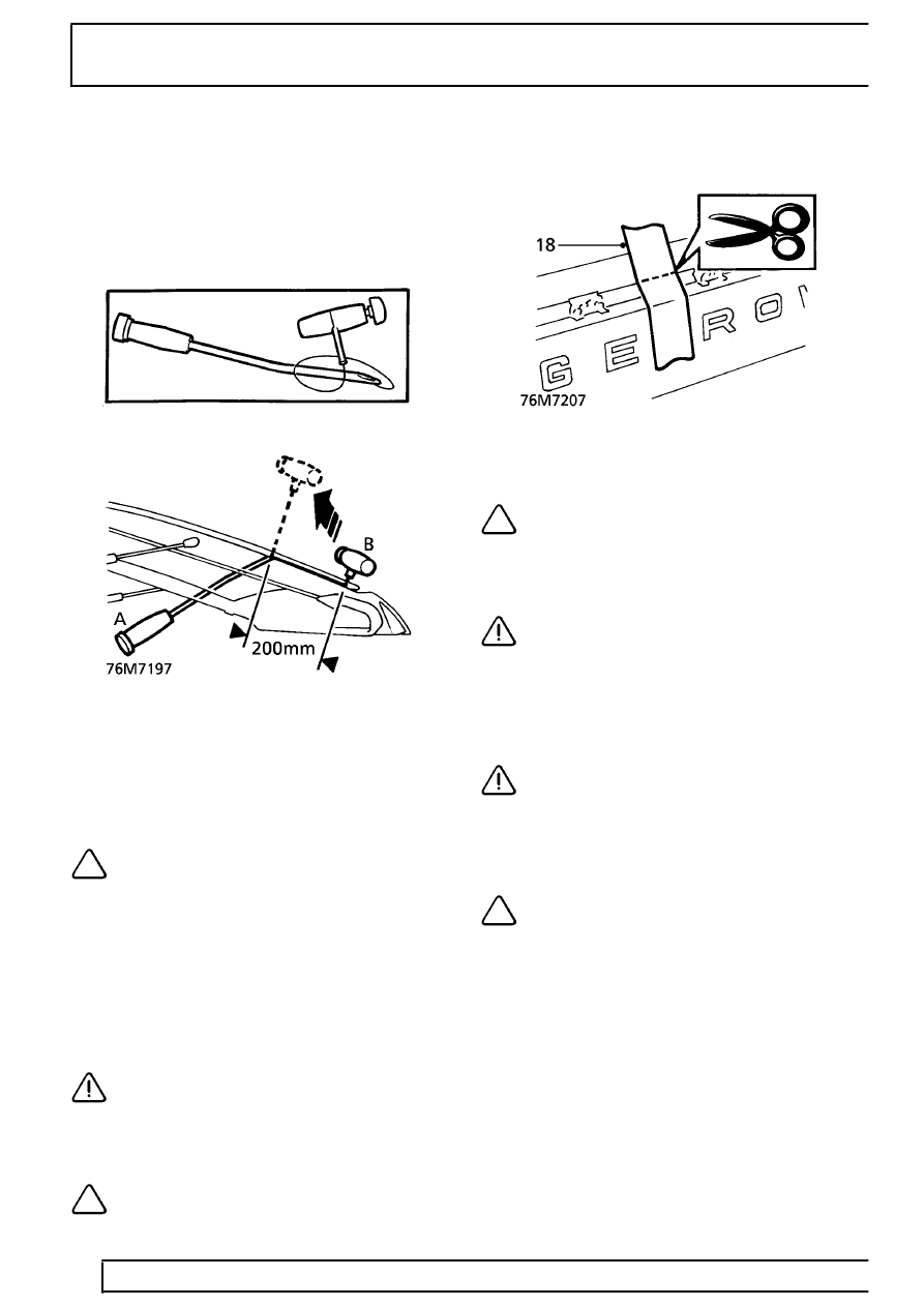
Removal Using Cutting Wire Handles
12. Using a sharp knife, cut through P.U. sealer at
side of backlight.
13. Insert cutting wire through knife cut and fit
handles, as shown, with approximately 200mm
of wire between handles.
14. With assistance, wedge tube of handle ’A’
between glass and body, ahead of the cutting
position, and carefully cut the sealer using a
continuous pull on handle ’B’ from the outside.
Cut side and top edges first. Attach suction lifters
and restrain glass as last of sealant is cut.
NOTE: When cutting along lower edge,
manoeuvre wire between glass edge and
finisher clips to reduce strain on wire.
15. With assistance, remove backlight glass.
Refit
16. Carefully cut old sealer from body flange to
obtain a smooth surface, approximately 2mm
thick.
CAUTION: Do not cut down to painted
surface.
17. Renew broken finisher clips as necessary.
Position finisher clips centrally on tailgate studs.
NOTE: Clips control height and seating of
lower glass edge.
18. Position and centralize new backlight to tailgate.
Apply tape reference mark to aid final fitment.
19. Position new backlight on felt covered surface.
20. Fit and centralize rubber finisher to top of glass.
NOTE: Finisher controls seating depth of
glass top edge.
21. Apply cleaning solvent to sealing surface of
glass and body flange.
CAUTION: Do not touch cleaned or primed
areas with fingers.
22. Shake primer tins for at least 30 seconds. Apply
body primer to sealing surface of body flange
using supplied applicator.
23. Apply glass primer to sealing surface of glass.
CAUTION: Use a separate applicator for
each primer.
24. Remove lid from sealer cartridge, remove
crystals, pierce membrane and fit pre-cut nozzle.
Fit cartridge to applicator gun.
NOTE: The profile of the nozzle must be
modified slightly to produce the required
bead section.
Parts & tools for this job Staging For Land Rover Range Rover
- TOOLTrim removal tool kitSearch: trim removal tool kit
- PARTTouch-up paintSearch: Land Rover touch up paint
- PARTPanel clip assortmentSearch: Land Rover panel clips assortment
Links open Amazon search results in a new tab. As an Amazon Associate I earn from qualifying purchases.