
TRANSFER BOX - DESCRIPTION (41 - TRANSFER BOX) (page 5 of 8)
- Make
- Land Rover
- Model
- Range Rover P38
- Section
- DESCRIPTION AND OPERATION
41
TRANSFER BOX
NEW RANGE ROVER
8
DESCRIPTION AND OPERATION
Transfer Box Electrical Components
Ratio control motor
The ratio control motor is located on the rear casing of
the transfer box and secured with four bolts. The
motor comprises a conventional single speed
permanent magnet type motor. The motor spindle has
a worm which engages with a worm wheel in a
housing at the end of the motor. The worm wheel is
attached to the spindle of the selector interlock spool
inside the transfer box.
The worm wheel also drives a motor encoder which
comprises four position switches. The transfer box
ECU provides a 5 V signal to each switch and
interprets the transfer box range by monitoring the
condition of each switch.
The transfer box ECU reads the motor position in the
form of a binary code with each switch either open or
closed circuit. The ECU measures between the
switches and an encoder ground on connector pin 19.
By using the combinations of the switches, the
transfer box ECU can calculate the transfer box
position and how the motor should operate to select
the desired range. If the transfer box should move to a
position outside the normal condition, i.e. left of high
range, the ECU can move the motor to the correct
position.
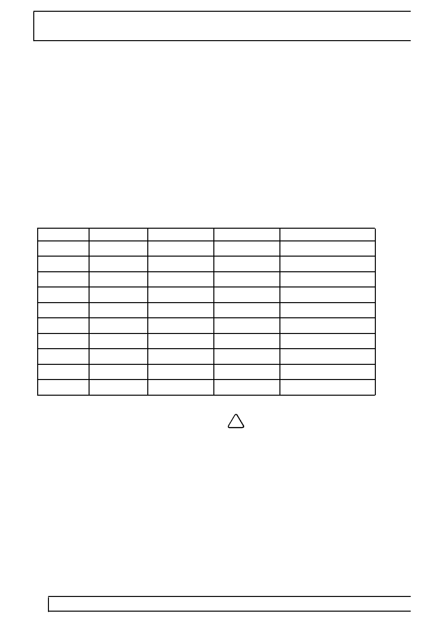
The table below shows the motor switch states and
the corresponding motor position for each state.
Switch 1
Switch 2
Switch 3
Switch 4
Motor position
Pin 17
Pin 32
Pin 31
Pin 7
Open
Open
Open
Closed
Left stop
Open
Closed
Open
Closed
Left of high
Closed
Closed
Open
Closed
High range
Closed
Closed
Closed
Closed
Right of high
Open
Closed
Closed
Closed
Zone 1
Open
Closed
Closed
Open
Neutral
Closed
Closed
Closed
Open
Zone 2
Closed
Open
Closed
Open
Low range
Closed
Open
Closed
Closed
Right stop
Speed sensor
The speed sensor is located in the rear casing and
secured with a screw. A toothed reluctor ring is
integrated on the rear output shaft. The inductive
speed sensor senses the reluctor ring and produces a
sine wave, impulse type signal as each tooth on the
reluctor ring passes the sensor.
The transfer box ECU processes the signal from the
speed sensor and compares this to a stored speed
value in the memory to determine if a range change is
allowed.
NOTE: The speed sensor is dedicated to
the transfer box ECU to determine if a
range change can be permitted.
Parts & tools for this job Staging For Land Rover Range Rover
- TOOLTorque wrenchSearch: 3/8 inch torque wrench
- TOOLSocket setSearch: socket set metric
- BOOKHaynes manualSearch: Haynes manual Land Rover Range Rover
Links open Amazon search results in a new tab. As an Amazon Associate I earn from qualifying purchases.