
TRANSFER BOX - DESCRIPTION (41 - TRANSFER BOX)
- Make
- Land Rover
- Model
- Range Rover P38
- Section
- DESCRIPTION AND OPERATION › TRANSFER BOX - DESCRIPTION
41
TRANSFER BOX
NEW RANGE ROVER
4
DESCRIPTION AND OPERATION
TRANSFER BOX - DESCRIPTION
General
All models are fitted with a Borg Warner transfer box.
The transfer box is a four wheel drive, two speed ratio
reducing gearbox with high and low range outputs
selected electrically by the driver.
A differential is fitted between the front and rear output
shafts to allow the propeller shafts to rotate at different
speeds when the vehicle is cornering. Drive to the
front propeller shaft is through a viscous coupling,
which eliminates the requirement for a differential
lock.
The high and low ranges are selected by the driver.
On manual transmission vehicles a switch is located
on the fascia and when pressed selects low range. On
automatic transmission vehicles high and low ranges
are selected by moving the auto transmission selector
lever across the H-gate to the required position.
On all vehicles, when the transfer box has changed to
high range, ’HIGH’ is displayed momentarily in the
instrument pack message centre. On automatic
transmission vehicles, if low range is selected, the
message centre momentarily displays ’LOW’ and then
permanently displays ’L’. On manual transmission
vehicles the message centre permanently displays
’LOW’.
The high and low range selection is performed by a
ratio control motor located on the transfer box. The
motor is controlled by a Transfer Box ECU located
below the LH front seat. The ECU is connected
electrically to other ECU’s to ensure that all conditions
for a successful range change are correct. The
transfer box ECU receives inputs and provides
outputs to/from the following ECU’s:
•
Body electrical Control Module (BeCM)
•
Electronic Automatic Transmission (EAT) ECU
•
Engine Control Module (ECM) (NAS only).
High/low range selection - Automatic transmission
vehicles
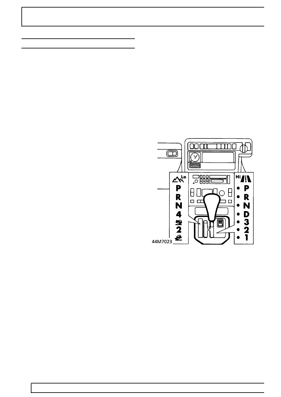
On automatic transmission vehicles, high and low
range selection is performed using the transmission
selector lever. The selector lever assembly consists of
a lever and a cover attached to a cast base. The base
is located on a gasket and secured to the
transmission tunnel.
The base has an ’H’ pattern for the lever to move in.
The lever is hinged to the base and is moved across
the ’H’ pattern to select HI or LO range operating a
microswitch located in the base. The driver’s side of
the ’H’ pattern is the high range selection in all
markets.
The cover incorporates LED lever position indicators
for high and low range gear selection. Operation of
the LED indicators are controlled by the BeCM. The
selected range is displayed by the LED’s being
illuminated brightly, with the unused range LED’s
dimmed. An electrical connector at the rear of the
cover connects the selector lever assembly to the
vehicle wiring.
High/low range selection - Manual transmission
vehicles
On manual transmission vehicles, high and low range
selection is performed using a latching pushbutton
switch on the fascia. The switch has an indicator lamp
which flashes when the transfer box is changing range
and is permanently illuminated in low range.
Parts & tools for this job Staging For Land Rover Range Rover
- TOOLTorque wrenchSearch: 3/8 inch torque wrench
- TOOLSocket setSearch: socket set metric
- BOOKHaynes manualSearch: Haynes manual Land Rover Range Rover
Links open Amazon search results in a new tab. As an Amazon Associate I earn from qualifying purchases.