
Supplementary Restraint System (SRS) Precautions (page 5 of 7)
- Make
- Land Rover
- Model
- Range Rover L322 Range Rover Service Procedures
GENERAL INFORMATION
03-25
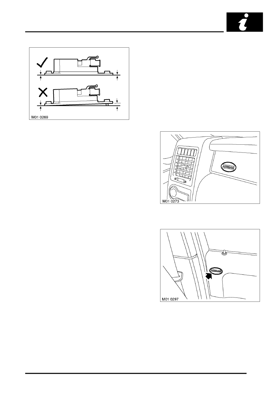
Ensure the side impact crash sensors are installed
correctly. There must be no gap between the sensor
and the mounting. Use either the fixings supplied
with the replacement or new fixings and tighten to the
correct torque.
CAUTION: Take extra care when painting or
carrying out bodywork repairs in the vicinity of
the crash sensors. Avoid direct exposure of the
crash sensors or link harnesses to heat guns,
welding or spraying equipment. Take care not to
damage sensor or harness when refitting
components.
Rotary coupler precautions
CAUTION: Always follow the procedure for fitting
and checking the rotary coupler as instructed in
the SRS repairs section. Comply with all safety
and installation procedures to ensure the system
functions correctly. Observe the following
precautions:
l
Do not unlock and rotate the rotary coupler
when it is removed from the vehicle.
l
Do not turn the road wheels when the rotary
coupler is removed from the vehicle.
l
Always ensure the rotary coupler is removed
and installed in its central position and with
the front road wheels in the straight ahead
position - refer to SRS repair section for the
correct removal and installation procedure.
l
If a new rotary coupler is being installed,
ensure the locking tab holding the coupler's
rotational position is not broken; units with a
broken locking tab must not be used.
Airbag location labels
Airbag location labels are displayed at various
positions in the vehicle. SRS components have
additional warning labels displayed on them to
indicate that particular care is needed when handling
them. These include airbag modules, crash sensors,
and seat belt pre-tensioners.
WARNING: It is imperative that before any work
is undertaken on the SRS system, the
appropriate information is read thoroughly.
NOTE: The following list indicates possible locations
and content for warning labels. The exact positions
and content may vary dependent on model year,
legislation and market trends.
Passenger side fascia label
Driver/passenger door label
Parts & tools for this job Staging For Land Rover Range Rover
- TOOLOBD2 scanner with SRSSearch: OBD2 scanner ABS SRS
- TOOLTrim removal tool kitSearch: trim removal tool kit
Links open Amazon search results in a new tab. As an Amazon Associate I earn from qualifying purchases.