
Drive shaft - rear (page 2 of 2)
- Make
- Land Rover
- Model
- Range Rover L322 Range Rover Service Procedures
- Section
- REPAIRS
DRIVESHAFTS
47-16
REPAIRS
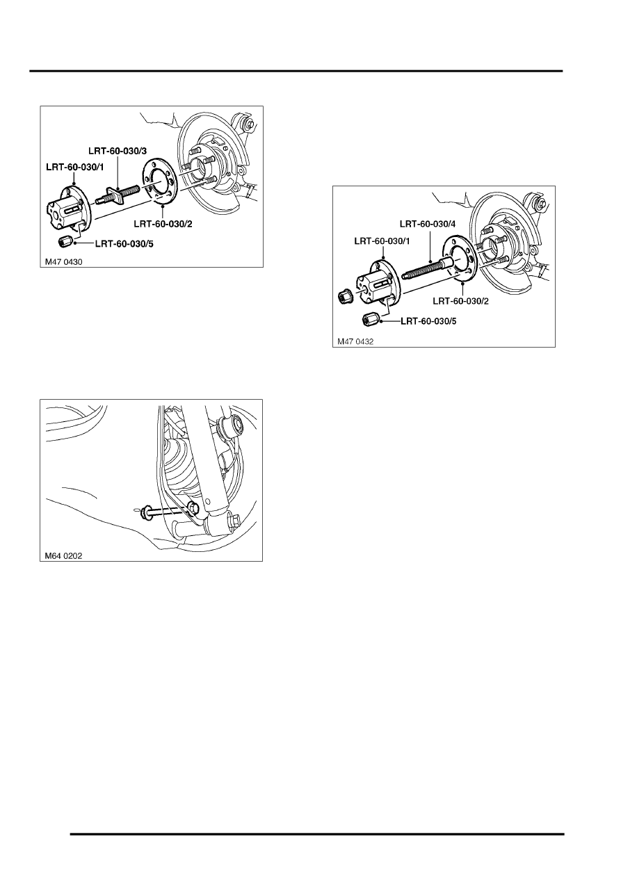
7. Fit centre screw LRT-60-030/3 to LRT-60-030/
1 and fit to hub with spacer LRT-60-030/2.
Secure with nuts LRT-60-030/5.
8. Tighten centre screw to press drive shaft from
flange.
9. Remove tools.
10. Position jack to support the lower arm.
11. Remove nut and bolt securing lower arm to
hub.
12. Lower support jack.
13. Release drive shaft from differential.
14. Release drive shaft from hub, and with
assistance, raise upper arm and remove drive
shaft.
Refit
1. Clean end of drive shaft and location in
differential.
2. Clean drive shaft and flange splines.
3. Lightly lubricate splines and oil seal running
surface.
LUBRICANTS AND SEALANTS,
Lubrication.
4. Clean lower arm and hub mating faces.
5. Locate drive shaft to differential and hub.
6. Align hub to lower arm, fit and lightly tighten nut
and bolt.
CAUTION: Nuts and bolts must be tightened
with vehicle at normal ride height.
7. Fit LRT-60-030/4 to drive shaft.
8. Fit LRT-60-030/1 with spacer LRT-60-030/2
and secure with nuts LRT-60-030/5.
9. Fit nut to LRT-60-030/4 and tighten nut to pull
drive shaft into drive flange.
10. Remove tools.
11. Fit brake disc.
12. With an assistant applying the brakes, fit new
hub nut and tighten to 420 Nm (311 lbf.ft).
13. Stake nut to shaft.
14. Clean bolt plates, position plates, fit new bolts
securing drive shaft to differential drive flange
and tighten to 40 Nm (30 lbf.ft) plus a further
60
°
.
15. Fit road wheel and tighten nuts to 140 Nm (103
lbf.ft).
16. Remove stands and lower vehicle.
17. Tighten bolt securing lower arm to hub to 250
Nm (184 lbf.ft).
Parts & tools for this job Staging For Land Rover Range Rover
- PARTRear wheel bearingSearch: Land Rover Range Rover rear wheel bearing
- TOOLBearing puller kitSearch: wheel bearing puller kit
- PARTCV boot kitSearch: Land Rover Range Rover cv boot kit
Links open Amazon search results in a new tab. As an Amazon Associate I earn from qualifying purchases.