
Valve Block and Solenoid Valves
- Make
- Land Rover
- Model
- Range Rover L322 Range Rover System Description and Operation
- Section
- Description › Valve Block and Solenoid Valves
AUTOMATIC TRANSMISSION – ZF 5HP24
44-2-16 DESCRIPTION AND OPERATION
The crescent spacer is fixed in its position by a pin and is located between the ring gear and the impeller. The impeller
is driven by the drive from the torque converter which is located a needle roller bearing in the pump housing. The
impeller teeth mesh with those of the ring gear. When the impeller is rotated, the motion is transferred to the ring gear
which rotates in the same direction.
The rotational motion of the ring gear and the impeller collects fluid from the intake port in the spaces between the
teeth. When the teeth reach the crescent spacer, the oil is trapped in the spaces between the teeth and is carried with
the rotation of the gears. The spacer tapers near the outlet port. This reduces the space between the gear teeth
causing a build up of fluid pressure as the oil reaches the outlet port. When the teeth pass the end of the spacer the
pressurised fluid is passed to the outlet port.
The fluid emerging from the outlet port is passed through the fluid pressure control valve. At high operating speeds
the pressure control valve maintains the output pressure to the gearbox at a predetermined maximum level. Excess
fluid is relieved from the pressure control valve and is directed, via the main pressure valve in the valve block, back
to the pump inlet port. This provides a pressurised feed to the pump inlet which prevents cavitation and reduces pump
noise.
Valve Block and Solenoid Valves
The valve block is located in the bottom of the transmission and is covered by the fluid pan. The valve block houses
electrical actuators, and control valves which provide all electro-hydraulic control for all transmission functions. The
valve block comprises the following components:
l
Five pressure regulator solenoids
l
Three shift control solenoids
l
Six dampers
l
Twenty one hydraulic spool valves
l
Manually operated selector valve.
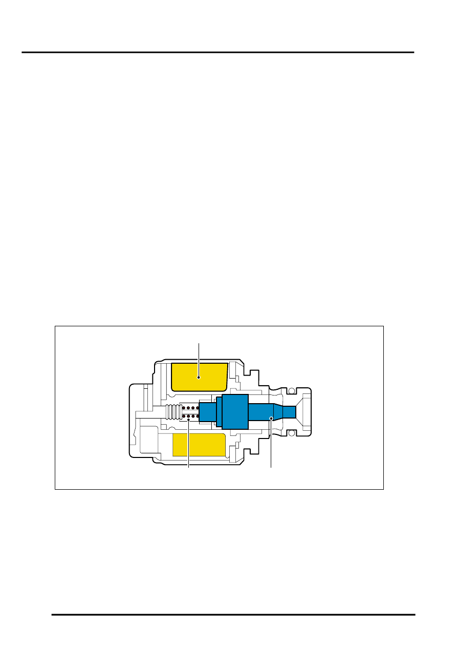
Pressure Regulator Solenoids
1 Coil winding
2 Valve
3 Spring
Five Electronic Pressure Regulator Solenoids (EPRS) are located in the valve block. The solenoids are controlled by
PWM signals from the EAT ECU. The solenoids convert the electrical signals into hydraulic control pressure
proportional to the signal to actuate the spool valves for precise transmission operation. EPRS4 is used for pressure
regulation for the torque converter lock-up clutch.
M44 1825
1
2
3
Parts & tools for this job Staging For Land Rover Range Rover
- PARTEngine gasket setSearch: Land Rover Range Rover engine gasket set
- TOOLTorque wrenchSearch: 3/8 inch torque wrench
- TOOLFeeler gauge setSearch: feeler gauge set
Links open Amazon search results in a new tab. As an Amazon Associate I earn from qualifying purchases.