
Camshaft timing belt (page 5 of 8)
- Make
- Land Rover
- Model
- Freelander Service Procedures
- Section
- REPAIRS
ENGINE - K SERIES KV6
12-3-62 REPAIRS
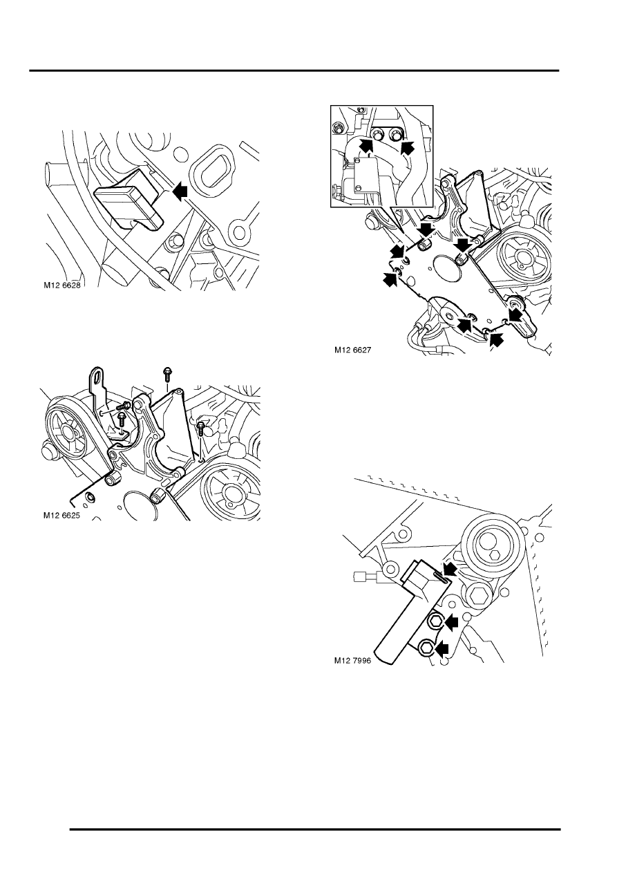
30. Depress and hold down dipstick tube locking
collar, remove dipstick tube from engine sump.
31. Remove rubber blanking plug from around
camshaft timing belt tensioner.
32. Remove 3 bolts securing engine front mounting
plate and lifting bracket to cylinder block.
33. Remove bolt securing lifting bracket to RH
cylinder head and remove lifting bracket.
34. Remove 2 bolts securing IRD support bracket
to engine front mounting plate.
35. Remove 5 bolts and 2 pillar bolts securing
engine front mounting plate to cylinder block.
36. With care, release and remove front mounting
plate from engine.
37. Insert a suitable 1.5 mm diameter pin through
hole in tensioner body and into hole in plunger.
NOTE: If holes in body and plunger are not
aligned, move tensioner backplate using a
suitable broad bladed screwdriver; this will
move plunger sufficiently to enable pin to be
inserted.
Parts & tools for this job Staging For Land Rover Freelander
- PARTTiming belt kitSearch: Land Rover Freelander timing belt kit
- TOOLEngine timing tool setSearch: Land Rover engine timing tool set
- TOOLTorque wrenchSearch: 3/8 inch torque wrench
Links open Amazon search results in a new tab. As an Amazon Associate I earn from qualifying purchases.