
ENGINE - K SERIES KV6 (page 5 of 8)
- Make
- Land Rover
- Model
- Freelander Service Procedures
ENGINE - K SERIES KV6
OVERHAUL 12-3-111
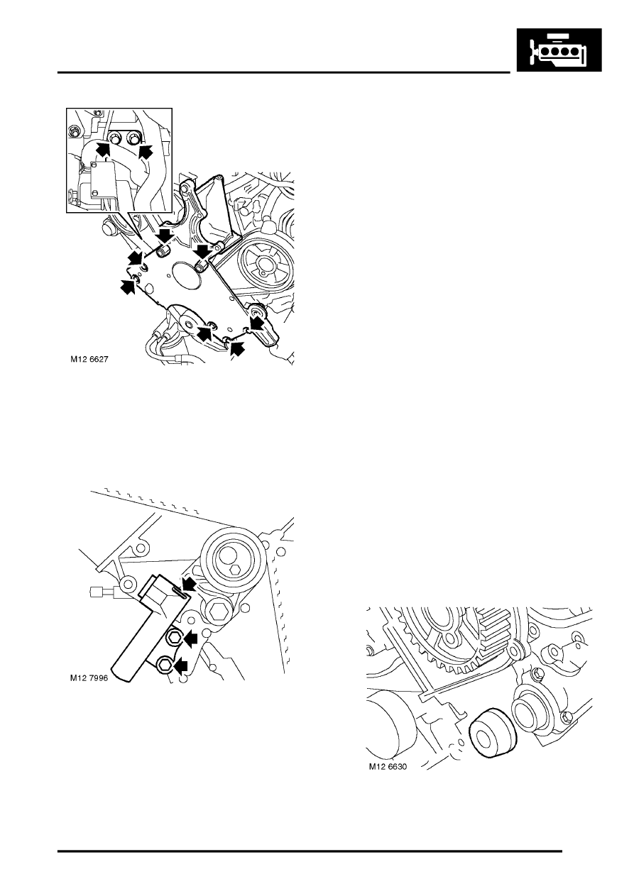
27. Remove 5 bolts and 2 pillar bolts securing
engine front mounting plate to cylinder block.
28. Remove 2 bolts securing IRD support bracket
to engine front mounting plate.
29. With care, release and remove front mounting
plate from engine.
30. Fit a suitable 1.5 mm diameter pin through hole
in tensioner body and into hole in plunger.
NOTE: If holes in body and plunger are not
aligned, move tensioner backplate using a
broad bladed screwdriver; this will move the
plunger sufficiently to align the holes and allow
the pin to be inserted.
31. Remove and discard 2 Patchlok bolts securing
tensioner to cylinder block and remove
tensioner.
CAUTION: Exercise great care when
removing bolts, do not apply excessive
torque. If bolts appear to be seized, apply
suitable anti-seize lubricant prior to
removing bolts. DO NOT loosen Allen screw
securing tensioner pulley.
32. If camshaft timing belt is to be refitted, mark
direction of rotation on timing belt before
removal.
33. With care, ease camshaft timing belt from
gears using fingers only and remove timing
belt.
CAUTION: Do not rotate crankshaft or
camshafts with timing belt removed.
CAUTION: Camshaft timing belt must be
replaced if cylinder head is to be removed or
new drive gears, tensioner or coolant pump
are to be fitted. Camshaft timing belts must
be stored and handled with care. Always
store a camshaft timing belt on its edge with
a bend radius greater than 50 mm (2.0 in).
Do not use a camshaft timing belt that has
been twisted or bent double as this will
damage the reinforcing fibres. Do not use a
camshaft timing belt if debris other than belt
dust is found in timing belt covers. Do not
use a camshaft timing belt if partial engine
seizure has occurred. Do not use a
camshaft timing belt if mileage exceeds
72,000 km (45,000 miles). Do not use an oil
or coolant contaminated timing belt, cause
of contamination must be rectified.
34. Remove and discard LH and RH exhaust
camshaft cap seals.
Parts & tools for this job Staging For Land Rover Freelander
- PARTEngine gasket setSearch: Land Rover Freelander engine gasket set
- TOOLTorque wrenchSearch: 3/8 inch torque wrench
- TOOLFeeler gauge setSearch: feeler gauge set
Links open Amazon search results in a new tab. As an Amazon Associate I earn from qualifying purchases.