
Steering Rack Operation
- Make
- Land Rover
- Model
- Freelander System Description and Operation
- Section
- Operation › Steering Rack Operation
STEERING
57-12
DESCRIPTION AND OPERATION
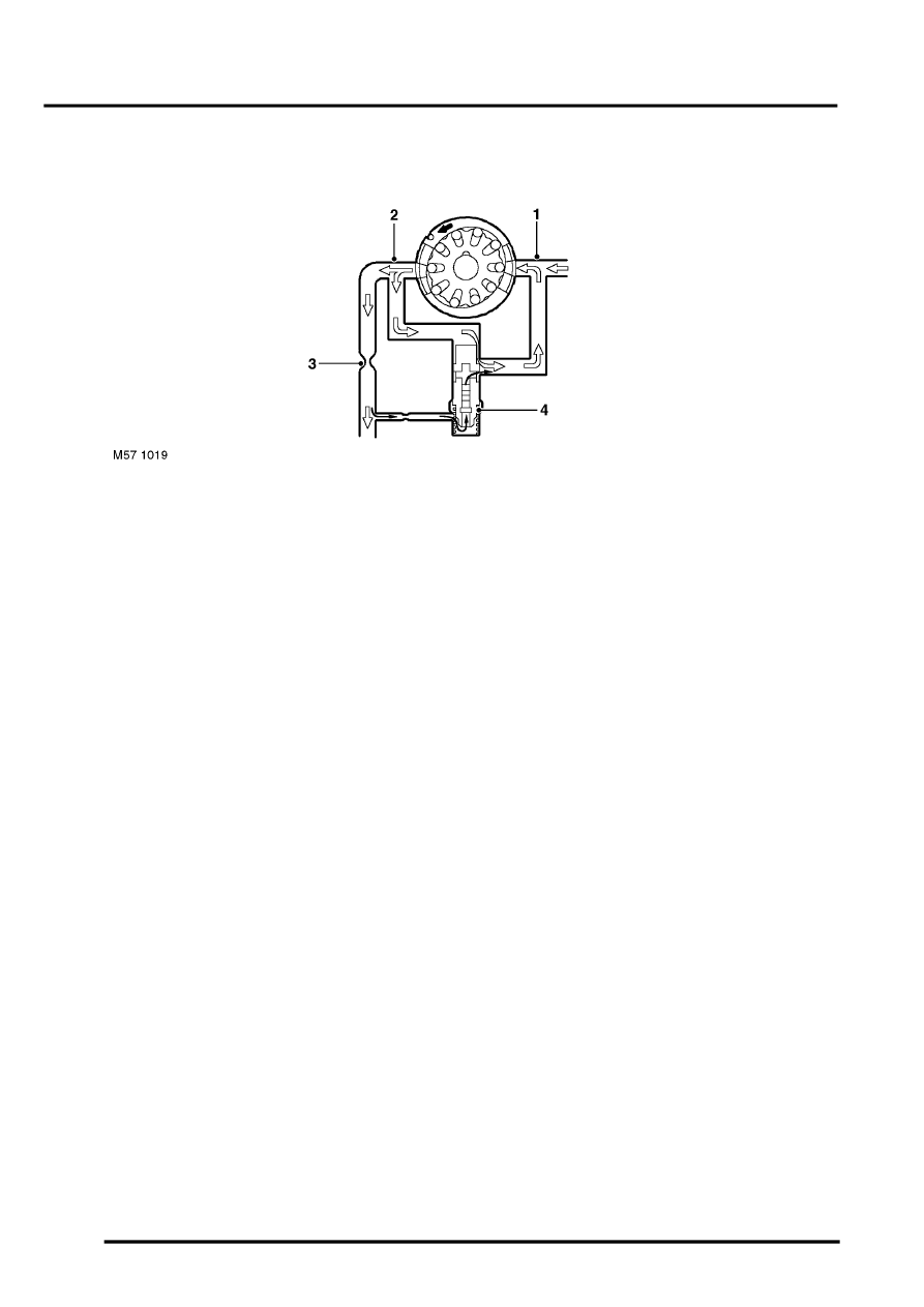
Pump Pressure Relief Valve Operation
1 Inlet port
2 Discharge port
3 Metering orifice
4 Pressure relief valve
The pressure relief valve is located in the centre of the flow control valve. If the pressure on the discharge side of the
metering orifice reaches a predetermined level, a spring loaded ball in the centre of the valve will lift from its seat and
allow pressurized fluid to recirculate within the pump.
The pressure relief valve will operate if the discharge from the pump is restricted, steering held at full lock. If the
discharge from the pump is completely blocked, all fluid discharged will be recirculated through the pump. As no fresh
fluid is drawn into the pump from the reservoir, the fluid temperature inside the pump will increase quickly.
Consequentially, periods of operation of full lock should be kept to a minimum to avoid overheating the pump and the
fluid within it.
Steering Rack Operation
Rotary movement of the steering wheel is transferred via the steering column to the input shaft of the valve unit on
the steering rack. The rotary movement of the input shaft is converted into linear movement of the steering rack
through the rack and pinion. With the engine running and the PAS pump operating, pressurised fluid is available to
the steering rack for power assistance.
Neutral Position
With no movement of the steering wheel being applied, the slots in the outer sleeve and the input shaft are so aligned
that the fluid flows across the valve unit with minimal restriction. Some pressure is applied to the full area port and the
annulus port which in turn is felt at either side of the piston in the hydraulic cylinder. With the forces approximately
equal on each side of the cylinder, the steering remains in the neutral position. Fluid delivered from the PAS pump is
returned from the valve unit via the fluid cooler back to the reservoir. With minimal restriction across the valve unit and
through the return hose, the pressure applied to each side of the piston is very low.
Parts & tools for this job Staging For Land Rover Freelander
- TOOLTie rod end toolSearch: tie rod end puller
- TOOLBall joint separatorSearch: ball joint separator
- FLUIDPower steering fluidSearch: Land Rover power steering fluid
Links open Amazon search results in a new tab. As an Amazon Associate I earn from qualifying purchases.