
Torque Converter
- Make
- Land Rover
- Model
- Freelander System Description and Operation
- Section
- Description › Torque Converter
AUTOMATIC GEARBOX - JATCO
DESCRIPTION AND OPERATION
44-17
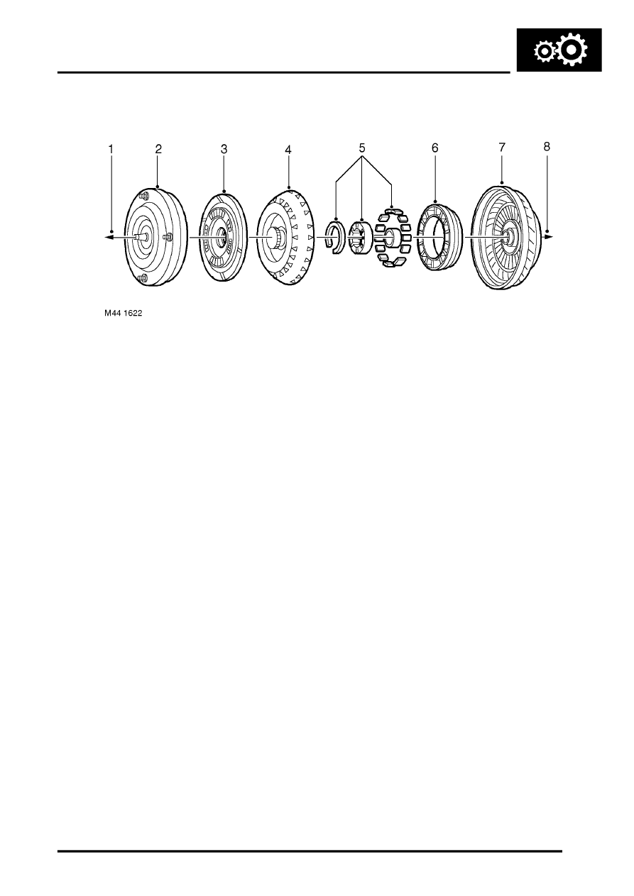
Torque Converter
1 To engine
2 Torque converter cover welded to the impeller
3 Lock-up clutch
4 Turbine
5 One-way clutch
6 Stator
7 Impeller
8 To gearbox
The torque converter is located inside the torque converter housing which is on the engine side of the gearbox casing.
The torque converter acts as the coupling element between the engine and gearbox. The driven power from the
engine is transmitted hydraulically and mechanically in certain gears and operating conditions, through the torque
converter lock-up clutch to the gearbox. The torque converter is connected to the engine by a drive plate.
The torque converter consists of an impeller, stator and turbine. The engine drives the impeller, while the turbine
drives the gearbox.
The stator is situated between the impeller and turbine on a one-way clutch. The impeller picks up fluid and throws it
out into the turbine, thereby causing it also to rotate and transmit power.
The stator redirects the fluid thrown back by the turbine, so that it re-enters the impeller in the same direction of
rotation as the impeller and at the most efficient angle.
The one-way clutch prevents the stator from moving backwards, so that this accurate redirection of fluid can be
achieved. When the engine is idling the impeller throws out very little fluid. The turbine is not forced to turn, and the
power is not transmitted to the gearbox.
As engine speed increases the impeller throws out more fluid. The turbine begins to turn and picks up speed as the
engine speed rises. As the speed of the turbine increases the fluid is thrown against the back of the stator, causing it
to turn in the same direction.
When turbine speed approaches impeller speed, centrifugal force in both units is almost equal and all three
components move at nearly the same rate. This is called the 'coupling point'.
The torque multiplication or drive ratio varies until a one to one coupling point is reached.
To achieve the power required to climb a hill, the driver depresses the accelerator pedal and the torque converter
reacts by increasing the torque multiplication.
When driving on a flat road at cruising speed, the power required is not as great and therefore, the torque converter
stays at one to one.
Parts & tools for this job Staging For Land Rover Freelander
- PARTTransmission filter kitSearch: Land Rover Freelander transmission filter kit
- FLUIDAutomatic transmission fluidSearch: Land Rover automatic transmission fluid
- TOOLFluid transfer pumpSearch: fluid transfer pump
Links open Amazon search results in a new tab. As an Amazon Associate I earn from qualifying purchases.