
System cable loom - r.r.
- Make
- Lancia
- Model
- Thesis Factory Service Manual
- Year
- 2002–2009
- Section
- Petrol fuel injection system › System cable loom - r.r.
SYSTEM CABLE LOOM - R.R.
Removing
- Position the vehicle on a lift.
- Make sure that the ignition key is in the OFF position, then disconnect the negative battery terminal.
See in Op. 7040D50 ENGINE COMPARTMENT UPPER SOUND INSULATION SHIELD - R.R.
See in Op. 1016A40 Ignition COIL COVER on cylinder head - R.R.
See in Op. 1048A28 vacuum air circuit resonator pipe - r+r
See in Op. 1048A48 HOSE BETWEEN RESONATOR AND THROTTLE CASING - R.R.
See in Op. 1048A21 AIR INLET HOSE FROM INTAKE TO FILTER - R.R.
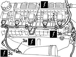
1. Disconnect the electrical connections from the ignition coils.
| Description | Connector | |
|---|---|---|
| 1 | Ignition coil | A030A |
| Description | Connector | |
|---|---|---|
| 1 | Ignition coil | A030B |
| Description | Connector | |
|---|---|---|
| 1 | Ignition coil | A030C |
| Description | Connector | |
|---|---|---|
| 1 | Ignition coil | A030D |
| Description | Connector | |
|---|---|---|
| 1 | Ignition coil | A030E |
2. Release the electrical wiring for the ignition coils from the fastenings on the tappet cover.
3. Disconnect the electrical connection (3a) for the front Lambda sensor, the electrical connection (3b) for the rear Lambda sensor and the electrical connection (3c) for the air conditioning compressor coupling.
| Description | Connector | |
|---|---|---|
| 3a | Lambda sensor on catalyzer | K017 |
| Description | Connector | |
|---|---|---|
| 3b | Lambda sensor on catalyzer 2 | K018 |
| Description | Connector | |
|---|---|---|
| 3c | Air conditioning compressor engagement electro-magnet | L020 |
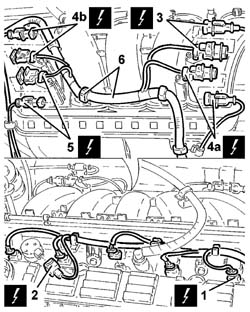
1. Disconnect the electrical connections from the injectors.
| Description | Connector | |
|---|---|---|
| 1 | Injector | N070A |
| Description | Connector | |
|---|---|---|
| 1 | Injector | N070B |
| Description | Connector | |
|---|---|---|
| 1 | Injector | N070C |
| Description | Connector | |
|---|---|---|
| 1 | Injector | N070D |
| Description | Connector | |
|---|---|---|
| 1 | Injector | N070E |
2. Disconnect the electrical connection from the phase transformer solenoid.
3. Disconnect the electrical connection for the cam angle sensor.
| Description | Connector | |
|---|---|---|
| 3 | Timing sensor | K047 |
4. Disconnect the electrical connections (4a) and (4b) for the detonation sensors.
| Description | Connector | |
|---|---|---|
| 4a | Detonation sensor - 2 | K050 |
| Description | Connector | |
|---|---|---|
| 4b | Detonation sensor - 2 | K051 |
5. Disconnect the electrical connection for the rpm sensor.
| Description | Connector | |
|---|---|---|
| 5 | Rpm sensor | K046 |
6. Release the system cable loom from the fastenings on the upper part of the modular intake manifold.
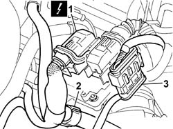
1. Disconnect the electrical connection for the injection/ignition control unit.
| Description | Connector | |
|---|---|---|
| 1 | Engine management control unit | M010A |
2. Release the system cable loom from the retaining bands on the injection/ignition control unit mounting.
3. Disconnect the dashboard/engine coupling.
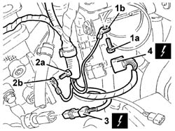
1. Undo the bolt (1a) and disconnect the earth lead (1b) from the injection/ignition control unit mounting.
2. Undo the bolt (2a) and disconnect the earth lead (1b) from the cylinder head.
3. Disconnect the electrical connection from the engine coolant temperature sensor.
4. Disconnect the electrical connection from the integrated throttle casing actuator.
| Description | Connector | |
|---|---|---|
| 4 | Integrated throttle casing actuator | N075 |
- Raise the vehicle on the lift.
1. Disconnect the electrical connection from the fuel vapour recovery solenoid valve.
| Description | Connector | |
|---|---|---|
| 1 | Fuel vapour recovery solenoid valve | L010 |
2. Disconnect the electrical connection from the switching control actuator enablement solenoid valve.
| Description | Connector | |
|---|---|---|
| 2 | Variable geometry solenoid valve | L015 |
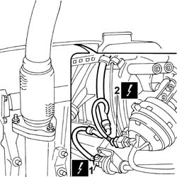
1. Disconnect the electrical connection for the engine oil level sensor.
| Description | Connector | |
|---|---|---|
| 1 | Engine oil level sensor | K032 |
2. Disconnect the earth lead from the starter motor.
3. Open the cover and disconnect the lead from the alternator.
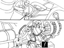
- Release the system cable loom from the fastenings on the lower part of the modular intake manifold.
- Remove the system cable loom.
Refitting
- Position the system cable loom and secure it to the lower part of the modular intake manifold.
- Connect the lead to the alternator and close the protective cover.
- Connect the earth lead to the starter motor.
- Connect the electrical connection for the engine oil level sensor.
| Description | Connector | |
|---|---|---|
| Engine oil level sensor | K032 |
- Connect the electrical connection for the switching control actuator enablement solenoid valve.
| Description | Connector | |
|---|---|---|
| Variable geometry solenoid valve | L015 |
- Connect the electrical connection for the fuel vapour recovery solenoid valve.
| Description | Connector | |
|---|---|---|
| Fuel vapour recovery solenoid valve | L010 |
- Lower the vehicle on the lift.
- Connect the electrical connection for the integrated throttle casing actuator.
| Description | Connector | |
|---|---|---|
| Integrated throttle casing actuator | N075 |
- Connect the engine coolant temperature sensor electrical connection.
- Connect the earth lead to the cylinder head and secure it using the bolt.
- Connect the earth lead to the injection/ignition control unit mounting and secure it using the bolt.
- Connect the dashboard/engine coupling.
- Fasten the system cable loom to the bands on the injection/ignition control unit mounting.
- Connect the electrical connection to the injection/ignition control unit.
| Description | Connector | |
|---|---|---|
| Engine management control unit | M010A |
- Fasten the system cable loom to the upper part of the modular intake manifold.
- Connect the electrical connection for the rpm sensor.
| Description | Connector | |
|---|---|---|
| Rpm sensor | K046 |
- Connect the electrical connections for the detonation sensors.
| Description | Connector | |
|---|---|---|
| Detonation sensor - 2 | K050 |
| Description | Connector | |
|---|---|---|
| Detonation sensor - 2 | K051 |
- Connect the electrical connection for the cam angle sensor.
| Description | Connector | |
|---|---|---|
| Timing sensor | K047 |
- Connect the electrical connection to the phase transformer solenoid.
- Connect the electrical connections to the injectors.
| Description | Connector | |
|---|---|---|
| Injector | N070A |
| Description | Connector | |
|---|---|---|
| Injector | N070B |
| Description | Connector | |
|---|---|---|
| Injector | N070C |
| Description | Connector | |
|---|---|---|
| Injector | N070D |
| Description | Connector | |
|---|---|---|
| Injector | N070E |
- Connect the electrical connection for the front Lambda sensor, the electrical connection for the rear Lambda sensor and the electrical connection for the air conditioning compressor coupling.
| Description | Connector | |
|---|---|---|
| Lambda sensor on catalyzer | K017 |
| Description | Connector | |
|---|---|---|
| Lambda sensor on catalyzer 2 | K018 |
| Description | Connector | |
|---|---|---|
| Air conditioning compressor engagement electro-magnet | L020 |
- Secure the electrical wiring for the ignition coils to the fastenings on the tappet cover.
- Connect the electrical connections to the ignition coils.
| Description | Connector | |
|---|---|---|
| Ignition coil | A030A |
| Description | Connector | |
|---|---|---|
| Ignition coil | A030B |
| Description | Connector | |
|---|---|---|
| Ignition coil | A030C |
| Description | Connector | |
|---|---|---|
| Ignition coil | A030E |
| Description | Connector | |
|---|---|---|
| Ignition coil | A030D |
See in Op. 1048A21 AIR INLET HOSE FROM INTAKE TO FILTER - R.R.
See in Op. 1048A48 HOSE BETWEEN RESONATOR AND THROTTLE CASING - R.R.
See in Op. 1048A28 vacuum air circuit resonator pipe - r+r
See in Op. 1016A40 Ignition COIL COVER on cylinder head - R.R.
See in Op. 7040D50 ENGINE COMPARTMENT UPPER SOUND INSULATION SHIELD - R.R.
- Connect the negative battery lead.
- Remove the vehicle from the lift.
Removing
- Position the vehicle on a lift.
- Open the boot, remove the cover on the left hand side and disconnect the negative battery lead.
See in Op. 4450B04 Right FRONT WHEEL (one) - R.R.
- Raise the vehicle on the lift.
See in Op. 7055B64 Engine compartment DUST SEAL in front wheel arch (one), left or right - R.R.
See in Op. 7055B54 PROTECTION/GUARD under engine - R.R.
See in Op. 7040D50 ENGINE COMPARTMENT UPPER SOUND INSULATION SHIELD - R.R.
See in Op. 1048A21 AIR INLET HOSE FROM INTAKE TO FILTER - R.R.
See in Op. 1048A28 vacuum air circuit resonator pipe - r+r
See in Op. 1088B10 Engine coolant SUPPLY RESERVOIR - R.R.
See in Op. 1008C10 Power unit REACTION ROD - Replace
1. Disconnect the electrical connection from the air flow meter.
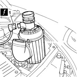
See in Op. 1048A11 COMPLETE AIR FILTER -R.R.
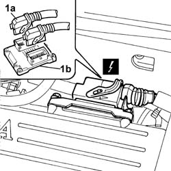
1. Disconnect the connectors (1a) from the engine management control unit (1b).
| Description | Connector | |
|---|---|---|
| 1a | Engine management control unit | M010A |
| Description | Connector | |
|---|---|---|
| 1a | Engine management control unit | M010B |
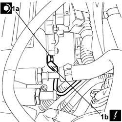
1. Undo the nut (1a) and disconnect the earth lead (1b) on the air chamber.
| Description | Connector | |
|---|---|---|
| 1b | Earth on engine | C040 |
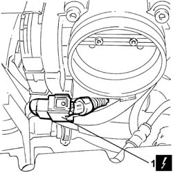
1. Disconnect the throttle casing connector.
| Description | Connector | |
|---|---|---|
| 1 | Integrated throttle casing actuator | N075 |
See in Op. 1072B50 Air CHAMBER - R.R.
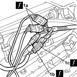
1. Remove the container positioned behind the air chamber and disconnect the two connectors (1a) for the rear Lambda sensors, the connector (1b) for the timing side detonation sensor and the coupling (1c) between the engine system cable and the vehicle wiring.
| Description | Connector | |
|---|---|---|
| 1a | Lambda sensor on catalyzer | K017 |
| Description | Connector | |
|---|---|---|
| 1a | Lambda sensor on catalyzer 2 | K018 |
| Description | Connector | |
|---|---|---|
| 1b | Detonation sensor - 2 | K050 |
| Description | Connector | |
|---|---|---|
| 1c | Air conditioning-heater front coupling | D008A |
See in Op. 2710A31 INTERMEDIATE DRIVE SHAFT - R.R.
See in Op. 1084B30 CARTRIDGE ENGINE OIL FILTER -R.R.
See in Op. 1076B84 EXHAUST PIPE BETWEEN RIGHT PRECONVERTER AND CATALYTIC CONVERTER - R.R.
See in Op. 1016A42 LEFT CYLINDER HEAD IGNITION COIL COVER - R.R.
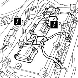
1. Disconnect the connectors for the ignition coils.
2. Disconnect the connectors for the injectors.
| Description | Connector | |
|---|---|---|
| 1 | Ignition coil | A030A |
| Description | Connector | |
|---|---|---|
| 1 | Ignition coil | A030B |
| Description | Connector | |
|---|---|---|
| 1 | Ignition coil | A030C |
| Description | Connector | |
|---|---|---|
| 1 | Ignition coil | A030D |
| Description | Connector | |
|---|---|---|
| 1 | Ignition coil | A030E |
| Description | Connector | |
|---|---|---|
| 1 | Ignition coil | A030F |
| Description | Connector | |
|---|---|---|
| 2 | Injector | N070A |
| Description | Connector | |
|---|---|---|
| 2 | Injector | N070B |
| Description | Connector | |
|---|---|---|
| 2 | Injector | N070C |
| Description | Connector | |
|---|---|---|
| 2 | Injector | N070D |
| Description | Connector | |
|---|---|---|
| 2 | Injector | N070E |
| Description | Connector | |
|---|---|---|
| 2 | Injector | N070F |
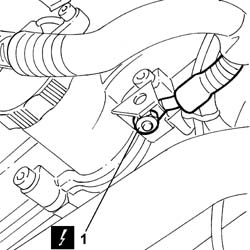
1. Undo the fixing bolt and disconnect the earth lead on the left head.
| Description | Connector | |
|---|---|---|
| 1 | Earth on engine | C040 |
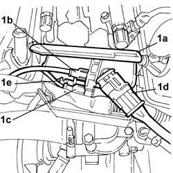
1. Open the container (1a) cover and disconnect the connectors (1b) and (1c) for the rear Lambda sensors, the connector (1d) for the detonation sensor and the coupling 91e) between the injection/ignition system wiring and the engine compartment front wiring.
| Description | Connector | |
|---|---|---|
| 1b | Lambda sensor on pre-catalyzer | K015 |
| Description | Connector | |
|---|---|---|
| 1c | Lambda sensor on pre-catalyzer -2 | K016 |
| Description | Connector | |
|---|---|---|
| 1d | Detonation sensor - 2 | K051 |
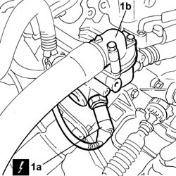
1. Disconnect the connector (1a) for the coolant temperature sensor on the thermostat unit (1b).
| Description | Connector | |
|---|---|---|
| 1a | I.E. engine temperature sensor | K045 |
1. Disconnect the connector for the oil pressure bulb.
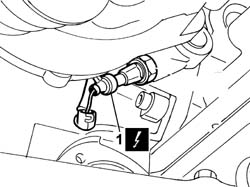
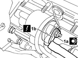
1. Disconnect the energizing cable on the alternator.
| Description | Connector | |
|---|---|---|
| 1 | Alternator | A010A |
| Description | Connector | |
|---|---|---|
| 1 | Alternator | A010B |
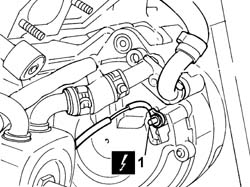
1. Undo the nut (1a) and disconnect the cable (1b) for the relay on the starter motor.
| Description | Connector | |
|---|---|---|
| 1b | Starter motor | A020A |
| Description | Connector | |
|---|---|---|
| 1b | Starter motor | A020B |
See in Op. 1080B39 RIGHT CATALYTIC PRECONVERTER - R.R. or Replace Gasket
- Raise the vehicle.
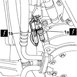
1. Disconnect the air conditioning compressor coupling supply connector (1a) (red cable) and the connector (1b) for the engine oil level warning light.
| Description | Connector | |
|---|---|---|
| 1a | Air conditioning compressor engagement electro-magnet | L020 |
| Description | Connector | |
|---|---|---|
| 1b | Engine oil level sensor | K032 |
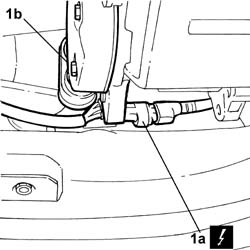
1. Disconnect the connector (1a) for the left precatalyzer Lambda sensor located near the climate control system compressor (1b).
| Description | Connector | |
|---|---|---|
| 1a | Lambda sensor on pre-catalyzer -2 | K016 |
- Check that all the lower wiring retaining bands are open, then lower the vehicle.
1. Remove the system cable loom (1a), complete with injector/coil cable ducts (1b).
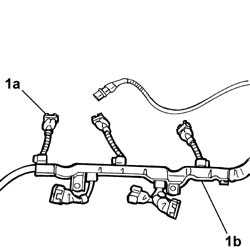
Refitting
- Position the cable loom and fasten the retaining bands.
- Connect the connector for the left precatalyzer Lambda sensor located near the climate control system compressor.
- Connect the air conditioning compressor coupling supply connector (red cable) and the connector for the engine oil level warning light.
| Description | Connector | |
|---|---|---|
| Air conditioning compressor engagement electro-magnet | L020 |
| Description | Connector | |
|---|---|---|
| Engine oil level sensor | K032 |
- Lower the vehicle.
See in Op. 1080B39 RIGHT CATALYTIC PRECONVERTER - R.R. or Replace Gasket
- Position the cable for the relay on the starter motor and tighten the fixing nut.
| Description | Connector | |
|---|---|---|
| Starter motor | A020A |
| Value - daNm | Fastening | Component | Ø | |
|---|---|---|---|---|
| 0.5 | Nut | STARTER MOTOR | M8 |
| Description | Connector | |
|---|---|---|
| Starter motor | A020B |
- Connect the alternator energizing cable and tighten the fixing nut to the recommended torque.
| Description | Connector | |
|---|---|---|
| Alternator | A010A |
| Value - daNm | Fastening | Component | Ø | |
|---|---|---|---|---|
| 0.5 | Nut | ALTERNATOR | M8 |
| Description | Connector | |
|---|---|---|
| Alternator | A010B |
- Connect the connector for the oil pressure bulb.
- Connect the connector for the coolant temperature sensor on the thermostat unit.
| Description | Connector | |
|---|---|---|
| 1 | I.E. engine temperature sensor | K045 |
- Connect the connectors for the rear Lambda sensors, the connector for the detonation sensor and the coupling between the injection/ignition wiring and the engine compartment front wiring, then close the container cover.
| Description | Connector | |
|---|---|---|
| Lambda sensor on pre-catalyzer | K015 |
| Description | Connector | |
|---|---|---|
| Lambda sensor on pre-catalyzer -2 | K016 |
| Description | Connector | |
|---|---|---|
| Detonation sensor - 2 | K051 |
- Connect the earth lead on the left head, tightening the fixing bolt.
- Connect the connectors for the ignition coils.
| Description | Connector | |
|---|---|---|
| Ignition coil | A030A |
| Description | Connector | |
|---|---|---|
| Ignition coil | A030B |
| Description | Connector | |
|---|---|---|
| Ignition coil | A030C |
| Description | Connector | |
|---|---|---|
| Ignition coil | A030D |
| Description | Connector | |
|---|---|---|
| Ignition coil | A030E |
| Description | Connector | |
|---|---|---|
| Ignition coil | A030F |
- Connect the connectors for the injectors.
| Description | Connector | |
|---|---|---|
| Injector | N070A |
| Description | Connector | |
|---|---|---|
| 2 | Injector | N070B |
| Description | Connector | |
|---|---|---|
| 2 | Injector | N070C |
| Description | Connector | |
|---|---|---|
| 2 | Injector | N070D |
| Description | Connector | |
|---|---|---|
| 2 | Injector | N070E |
| Description | Connector | |
|---|---|---|
| 2 | Injector | N070F |
See in Op. 1016A42 LEFT CYLINDER HEAD IGNITION COIL COVER - R.R.
See in Op. 1076B84 EXHAUST PIPE BETWEEN RIGHT PRECONVERTER AND CATALYTIC CONVERTER - R.R.
See in Op. 1084B30 CARTRIDGE ENGINE OIL FILTER -R.R.
See in Op. 2710A31 INTERMEDIATE DRIVE SHAFT - R.R.
- Connect the two connectors for the rear Lambda sensors, the connector for the timing side detonation sensor and the coupling between the engine system cable and the vehicle wiring, then position the protective container.
| Description | Connector | |
|---|---|---|
| Lambda sensor on catalyzer | K017 |
| Description | Connector | |
|---|---|---|
| Lambda sensor on catalyzer 2 | K018 |
| Description | Connector | |
|---|---|---|
| Detonation sensor - 2 | K050 |
| Description | Connector | |
|---|---|---|
| Air conditioning-heater front coupling | D008A |
See in Op. 1072B50 Air CHAMBER - R.R.
- Connect the throttle casing connector.
| Description | Connector | |
|---|---|---|
| Integrated throttle casing actuator | N075 |
- Connect the earth lead on the air chamber tightening the fixing nut.
- Connect the connectors to the engine management control unit.
| Description | Connector | |
|---|---|---|
| Engine management control unit | M010A |
| Description | Connector | |
|---|---|---|
| Engine management control unit | M010B |
- Connect the electrical connection to the air flow meter.
See in Op. 1008C10 Power unit REACTION ROD - Replace
See in Op. 1088B10 Engine coolant SUPPLY RESERVOIR - R.R.
See in Op. 1048A28 vacuum air circuit resonator pipe - r+r
See in Op. 1048A21 AIR INLET HOSE FROM INTAKE TO FILTER - R.R.
See in Op. 7040D50 ENGINE COMPARTMENT UPPER SOUND INSULATION SHIELD - R.R.
See in Op. 7055B54 PROTECTION/GUARD under engine - R.R.
See in Op. 7055B64 Engine compartment DUST SEAL in front wheel arch (one), left or right - R.R.
- Lower the vehicle.
See in Op. 4450B04 Right FRONT WHEEL (one) - R.R.
- Connect the negative battery lead, then close the boot.
- Remove the vehicle from the lift.
Removing
- Position the vehicle on a lift.
- Make sure that the ignition key is in the OFF position, then disconnect the negative battery terminal.
See in Op. 7040D50 ENGINE COMPARTMENT UPPER SOUND INSULATION SHIELD - R.R.
See in Op. 1016A40 Ignition COIL COVER on cylinder head - R.R.
See in Op. 1048A50 air inlet pipe to turbocharger - r + r
See in Op. 1048A21 AIR INLET HOSE FROM INTAKE TO FILTER - R.R.
1. Disconnect the electrical connections from the ignition coils (1a), the injectors (1b), the fuel vapour recovery solenoid valve (1c), the phase transformer actuator (1d) and the intake air temperature and pressure sensor (1e).
| Description | Connector | |
|---|---|---|
| 1a | Ignition coil | A030A |
| Description | Connector | |
|---|---|---|
| 1a | Ignition coil | A030B |
| Description | Connector | |
|---|---|---|
| 1a | Ignition coil | A030C |
| Description | Connector | |
|---|---|---|
| 1a | Ignition coil | A030D |
| Description | Connector | |
|---|---|---|
| 1a | Ignition coil | A030E |
| Description | Connector | |
|---|---|---|
| 1b | Injector | N070A |
| Description | Connector | |
|---|---|---|
| 1b | Injector | N070B |
| Description | Connector | |
|---|---|---|
| 1b | Injector | N070C |
| Description | Connector | |
|---|---|---|
| 1b | Injector | N070D |
| Description | Connector | |
|---|---|---|
| 1b | Injector | N070E |
| Description | Connector | |
|---|---|---|
| 1c | Fuel vapour recovery solenoid valve | L010 |
| Description | Connector | |
|---|---|---|
| 1e | Integrated air temperature sensor | K043 |
- Release the electrical wiring from the fastenings on the tappet cover and on the fuel manifold.
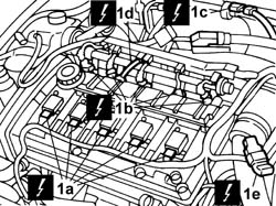
1. Disconnect the electrical connection for the front Lambda sensor (1a), the rear Lambda sensor (1b) and the air conditioning compressor coupling (1c).
| Description | Connector | |
|---|---|---|
| 1a | Lambda sensor on catalyzer | K017 |
| Description | Connector | |
|---|---|---|
| 1c | Air conditioning compressor engagement electro-magnet | L020 |
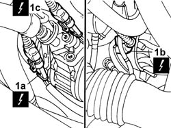
1. Disconnect the electrical connection for the turbocharger by-pass actuator.
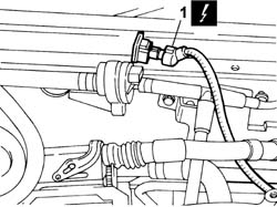
1. Disconnect the electrical connection from the flow meter (1a), the atmospheric pressure sensor (1b), the integrated throttle casing actuator (1c) and the engine coolant temperature sensor (1d).
| Description | Connector | |
|---|---|---|
| 1c | Integrated throttle casing actuator | N075 |
| Description | Connector | |
|---|---|---|
| 1d | I.E. engine temperature sensor | K045 |
- Release the system cable loom from the fastenings in the front section of the engine compartment.
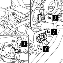
1. Disconnect the electrical connection from the injection/ignition control unit (1a), the detonation sensors (1b) and (1c), the cam angle (timing) sensor (1d) and the rpm sensor (1e).
| Description | Connector | |
|---|---|---|
| 1a | Engine management control unit | M010A |
| Description | Connector | |
|---|---|---|
| 1b | Detonation sensor - 2 | K050 |
| Description | Connector | |
|---|---|---|
| 1c | Detonation sensor - 2 | K051 |
| Description | Connector | |
|---|---|---|
| 1d | Timing sensor | K047 |
| Description | Connector | |
|---|---|---|
| 1e | Rpm sensor | K046 |
2. Disconnect the dashboard/engine coupling.
3. Disconnect the engine earth lead.
| Description | Connector | |
|---|---|---|
| 3 | Earth on engine | C040 |
- Release the system cable loom from the fastenings on the rear section of the modular intake manifold.
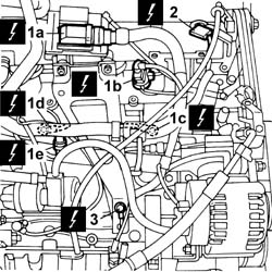
1. Disconnect the electrical connection for the insufficient engine oil pressure sensor (1a) and the engine oil level sensor (1b).
| Description | Connector | |
|---|---|---|
| 1a | Insufficient engine oil pressure sensor | K030 |
| Description | Connector | |
|---|---|---|
| 1b | Engine oil level sensor | K032 |
2. Disconnect the earth lead from the starter motor.
3. Open the cover and disconnect the lead from the alternator.
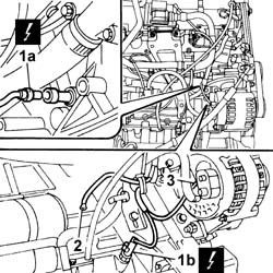
- Release the system cable loom from the fastenings in the rear section of the engine.
- Remove the system cable loom.
Refitting
- Position the system cable loom and secure it to the lower part of the modular intake manifold.
- Connect the lead to the alternator and close the protective cover.
- Connect the earth lead to the starter motor.
- Connect the electrical connection for the insufficient engine oil pressure sensor and the engine oil level sensor.
| Description | Connector | |
|---|---|---|
| Insufficient engine oil pressure sensor | K030 |
| Description | Connector | |
|---|---|---|
| Engine oil level sensor | K032 |
- Connect the electrical connection to the injection/ignition control unit, the detonation sensors, the cam angle (timing) sensor and the rpm sensor.
| Description | Connector | |
|---|---|---|
| Engine management control unit | M010A |
| Description | Connector | |
|---|---|---|
| Detonation sensor - 2 | K050 |
| Description | Connector | |
|---|---|---|
| Detonation sensor - 2 | K051 |
| Description | Connector | |
|---|---|---|
| Timing sensor | K047 |
| Description | Connector | |
|---|---|---|
| Rpm sensor | K046 |
- Connect the dashboard/engine coupling.
- Connect the earth lead to the cylinder head and secure it using the bolt.
| Description | Connector | |
|---|---|---|
| Earth on engine | C040 |
- Fasten the system cable loom to the fastenings in the rear section of the engine.
- Connect the electrical connection to the flow meter, the atmospheric pressure sensor, the integrated throttle casing actuator and the engine coolant temperature sensor.
| Description | Connector | |
|---|---|---|
| Integrated throttle casing actuator | N075 |
| Description | Connector | |
|---|---|---|
| I.E. engine temperature sensor | K045 |
- Connect the electrical connection for the turbocharger by-pass actuator.
- Connect the electrical connection for the front Lambda sensor, the rear Lambda sensor and the air conditioning compressor coupling.
| Description | Connector | |
|---|---|---|
| Lambda sensor on catalyzer | K017 |
| Description | Connector | |
|---|---|---|
| Air conditioning compressor engagement electro-magnet | L020 |
- Fasten the system cable loom to the fastenings in the front section of the engine compartment.
- Connect the electrical connections from the ignition coils, the injectors, the fuel vapour recovery solenoid valve, the phase transformer actuator and the intake air temperature and pressure sensor.
| Description | Connector | |
|---|---|---|
| Ignition coil | A030A |
| Description | Connector | |
|---|---|---|
| Ignition coil | A030B |
| Description | Connector | |
|---|---|---|
| Ignition coil | A030C |
| Description | Connector | |
|---|---|---|
| Ignition coil | A030D |
| Description | Connector | |
|---|---|---|
| Ignition coil | A030E |
| Description | Connector | |
|---|---|---|
| Injector | N070A |
| Description | Connector | |
|---|---|---|
| Injector | N070B |
| Description | Connector | |
|---|---|---|
| Injector | N070C |
| Description | Connector | |
|---|---|---|
| Injector | N070D |
| Description | Connector | |
|---|---|---|
| Injector | N070E |
| Description | Connector | |
|---|---|---|
| Fuel vapour recovery solenoid valve | L010 |
| Description | Connector | |
|---|---|---|
| Integrated air temperature sensor | K043 |
- Fasten the electrical wiring to the fastenings on the tappet cover and on the fuel manifold.
See in Op. 1048A21 AIR INLET HOSE FROM INTAKE TO FILTER - R.R.
See in Op. 1048A50 air inlet pipe to turbocharger - r + r
See in Op. 1016A40 Ignition COIL COVER on cylinder head - R.R.
See in Op. 7040D50 ENGINE COMPARTMENT UPPER SOUND INSULATION SHIELD - R.R.
- Connect the negative battery lead.
- Remove the vehicle from the lift.
Parts & tools for this job Staging For 2002 Lancia Thesis
- PARTFuel filterSearch: Lancia Thesis 2002 fuel filter
- TOOLFuel pressure test kitSearch: fuel pressure test kit
- TOOLFuel line disconnect toolSearch: fuel line disconnect tool
Links open Amazon search results in a new tab. As an Amazon Associate I earn from qualifying purchases.