
Air CHAMBER - R.R.
- Make
- Lancia
- Model
- Thesis Factory Service Manual
- Year
- 2002–2009
- Section
- Inlet and exhaust manifolds › Air CHAMBER - R.R.
Air CHAMBER - R.R.
Removing
- Open the boot, remove the cover on the left hand side and disconnect the negative battery lead.
See in Op. 7040D50 ENGINE COMPARTMENT UPPER SOUND INSULATION SHIELD - R.R.
See in Op. 1048A21 AIR INLET HOSE FROM INTAKE TO FILTER - R.R.
See in Op. 1048A28 vacuum air circuit resonator pipe - r+r
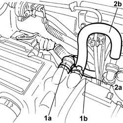
1. Disconnect the rapid connector (1a) for the fuel vapour recovery pipe (1b).
2. Open the band (2a) for the brake servo vacuum intake pipe (2b) and disconnect the pipe.
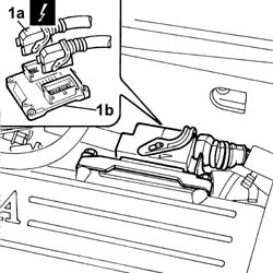
1. Disconnect the connectors (1a) from the engine management control unit (1b).
| Description | Connector | |
|---|---|---|
| 1a | Engine management control unit | M010A |
| Description | Connector | |
|---|---|---|
| 1a | Engine management control unit | M010B |
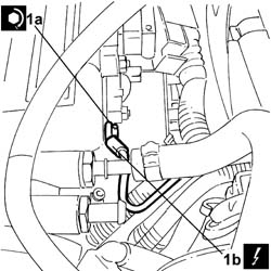
1. Undo the nut (1a) and disconnect the earth lead (1b) on the air chamber.
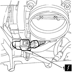
1. Disconnect the throttle casing connector
| Description | Connector | |
|---|---|---|
| 1 | Integrated throttle casing actuator | N075 |
1. Disconnect the rapid connector (1a) for the fuel pipe (1b) from the tank, undo the bolt (1c) fixing the pipe retaining duct (1d), then open the duct and release the pipe.
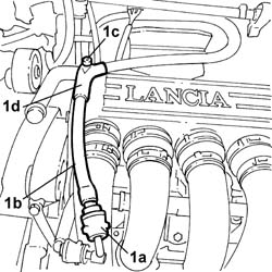
See in Op. 1072B42 INTAKE MANIFOLDS (all) - R.R. and Replace gasket
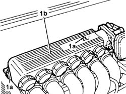
1. Undo the bolts (1a) and remove the air chamber (1b) and the gasket underneath.
Refitting
- Fit the air chamber and the gasket underneath and tighten the fixing bolts to the recommended torque.
| Value - daNm | Fastening | Component | Ø | |
|---|---|---|---|---|
| 0,9 | Bolt | INLET AIR DUCT | M6 |
See in Op. 1072B42 INTAKE MANIFOLDS (all) - R.R. and Replace gasket
- Position the fuel pipe in the duct and tighten the fixing bolt, then connect the rapid connector.
- Connect the throttle casing connector
| Description | Connector | |
|---|---|---|
| Integrated throttle casing actuator | N075 |
- Position the earth lead on the air chamber and tighten the fixing nut.
- Connect the connectors to the engine management control unit.
| Description | Connector | |
|---|---|---|
| Engine management control unit | M010A |
| Description | Connector | |
|---|---|---|
| Engine management control unit | M010B |
- Connect the vacuum intake pipe and close the retaining band.
- Connect the rapid connector for the fuel vapour recovery pipe.
See in Op. 1048A28 vacuum air circuit resonator pipe - r+r
See in Op. 1048A21 AIR INLET HOSE FROM INTAKE TO FILTER - R.R.
See in Op. 7040D50 ENGINE COMPARTMENT UPPER SOUND INSULATION SHIELD - R.R.
- Connect the negative battery terminal and position the cover on the left hand side of the luggage compartment.
- Operation not available
Parts & tools for this job Staging For 2002 Lancia Thesis
- PARTExhaust gasketSearch: Lancia Thesis 2002 exhaust gasket
- TOOLPenetrating oilSearch: penetrating oil
- TOOLOBD2 scannerSearch: OBD2 scanner
Links open Amazon search results in a new tab. As an Amazon Associate I earn from qualifying purchases.