
Left cylinder head – r.r. and replacing gasket
- Make
- Alfa Romeo
- Model
- GT Factory Service Manual
- Year
- 2003–2010
- Section
- Cylinder head/s › Left cylinder head – r.r. and replacing gasket
LEFT CYLINDER HEAD – R.R. AND REPLACING GASKET
Removing
Position the vehicle on the ramp.
Ensure that the ignition key is in OFF position, then disconnect the battery negative terminal (-).
| Name | Connector | |
|---|---|---|
| Battery | See A1B BATTERY ( BATTERY NEGATIVE ) |
Drain the air conditioner refrigerant
Op. 5040A10 EXPANSION/CONNECTION PIPE - R R.
Proceed with removal
Op. 4450B04 RIGHT FRONT WHEEL R R.
Proceed with removal
Op. 7055B64 LH OR RH REFLECTOR(ONE) ON REAR BUMPERS - R R.
Proceed with removal
Op. 7055B54 UNDER-ENGINE GUARD - R R.
Proceed with removal
Op. 1092G10 SINGLE ENGINE BELT R R.
Proceed with removal
Op. 1092A10 CRANKSHAFT SERVICES PULLEY - R.R..
Proceed with removal
Op. 1032D12 TIMING SYSTEM PROTECTIVE COVER(S) - R + R.
Proceed with removal
Op. 1016A42 LEFT HAND CYLINDER HEAD IGNITION COIL COVER - R+R.
Proceed with removal
Op. 5510C16 LEFT HAND CYLINDER HEAD IGNITION COIL - R+R.
Proceed with removal
Op. 1016A30 LEFT CAM COVER - R + R AND REPLACE GASKET.
Proceed with removal
Op. 1072B50 SLEEVES CONNECTING AIR CAPACITY BOX TO INLET MANIFOLD IS - R+R.
Proceed with removal
Op. 5510C18 RIGHT HAND CYLINDER HEAD IGNITION COIL - R+R.
Proceed with removal
Op. 1016A34 RIGHT-HAND CAM COVER - R + R AND REPLACE GASKET.
Proceed with removal
Op. 1032B10 TOOTHED TIMING BELT - R + R FOR TIMING ADJUSTMENT OR REPLACEMENT.
Proceed with removal
Op. 1048A48 THROTTLE HEATER SLEEVE - R R.
Proceed with removal
Proceed with removal
Op. 5530B52 BATTERY DRIP TRAY/SUPPORT - R.R..
Proceed with removal
Op. 1048A10 AIR CLEANER FILTERING ELEMENT - REPLACE.
Proceed with removal
Op. 7055B42 LH OR RH REFLECTOR(ONE) ON REAR BUMPERS - R R.
Proceed with removal
Op. 7210E10 R.R. FRONT BUMPER.
Proceed with the removal
Op. 5540B76 FRONT LIGHT CLUSTER WITH FOGLAMP ONE LH OR RH R R WITH INTERFERING PARTS REMOVED
(Right and left sides).
Proceed with removal
Op. 7025A34 BONNET LID LOCK (ONE) - R+R OR REPAIR.
Proceed with removal
- 7210A15 R.R. HEADLAMP HOUSING/FRONT WING CROSSMEMBER
Proceed with removal
Op. 1088B20 ENGINE COOLING RADIATOR - R + R.
Proceed with removal
Op. 1080B92 LEFT UPPER LAMBDA SENSOR R R.
Proceed with removal
Op. 1076A70 HEAT SHIELD FOR LEFT CATALYTIC PRECONVERTER R R.
Proceed with removal
Op. 1080B38 LEFT CATALYTIC PRECONVERTER R R OR REPLACE CYLINDER HEAD GASKET.
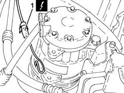
1. Disconnect the electrical connection for the air conditioning compressor electromagnet coupling.
| Name | Connector | |
|---|---|---|
| 1 | Air conditioning compressor engagement electro-magnet | See L20 AIR CONDITIONING COMPRESSOR ENGAGEMENT ELECTRO-MAGNET ( CONNECTORS ) |
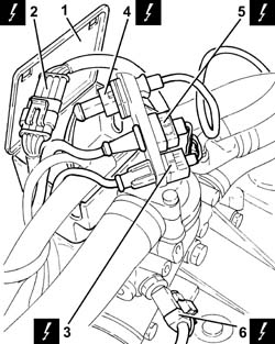
1. Open the electrical connections box cover.
2. Disconnect the electrical connection for the upper right Lambda sensor.
| Name | Connector | |
|---|---|---|
| 2 | Lambda sensor on pre-catalyzer -2 | See K16 LAMBDA SENSOR ON PRE-CATALYZER -2 ( CONNECTORS ) |
3. Disconnect the electrical connection for the rpm sensor.
| Name | Connector | |
|---|---|---|
| 3 | Rpm sensor | See K46 RPM SENSOR ( CONNECTORS ) |
4. Disconnect the electrical connection for the cam angle sensor.
| Name | Connector | |
|---|---|---|
| 4 | Timing sensor. | See K47 TIMING SENSOR. ( CONNECTORS ) |
5. Disconnect the electrical connection for the knock sensor flywheel side.
| Name | Connector | |
|---|---|---|
| 5 | Detonation sensor 1 | See K50 DETONATION SENSOR 1 ( CONNECTORS ) |
6. Disconnect the electrical connection from the engine coolant temperature sensor.
| Name | Connector | |
|---|---|---|
| 6 | Engine temperature sender unit | See K36 ENGINE TEMPERATURE SENDER UNIT ( CONNECTORS ) |
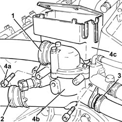
1. Loosen band and disconnect the upper coolant inlet hose to the radiator, thermostat side.
2. Loosen the band and disconnect the lower radiator coolant outlet hose from the radiator, thermostat side.
3. Loosen the band and disconnect the coolant supply pipe from the climate control heater, thermostat side.
4. Undo the bolts (4a) and remove the thermostat (4b) complete with electrical connections box (4c).
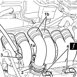
1. Undo the bolts (1a) and remove the intake pipes (1b).
2. Remove the gaskets.
Discharge the fuel system pressure with the tool connected to the bleed valves on the fuel pipe.
| Name | Country | |
|---|---|---|
| Rapid connector | 1.870.684.000 |
3. Disconnect the quick-release connector for the front fuel supply pipe, fuel pipe side.
4. Disconnect the electrical connections from the injectors.
| Name | Connector | |
|---|---|---|
| 4 | Injector | See N70 INJECTOR |
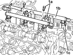
1. Undo the bolts (1a) and remove the fuel pipe (1b), complete with injectors (1c).
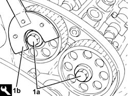
1. Undo the bolts (1a) fixing the left head driven pullies using the tool (1b) for counter-torque.
| Name | Country | |
|---|---|---|
| 1b | Counter-torque | 1.822.146.000 |
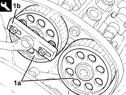
1. Remove the left head driven pulleys (1a) using the tool (1b).
| Name | Country | |
|---|---|---|
| 1b | Extractor | 1.860.954.001 |
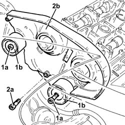
1. Undo the bolts (1a) and remove the timing belt fixed tensioners (1b).
2. Undo the bolts (2a) and remove the left rear protective timing cover (2b).
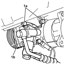
1. Undo the bolts (1a) and move the power assisted steering pump (1b) aside without disconnecting the pipes.
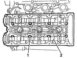
1. Undo the nuts fixing the left cylinder head using the tool.
| Name | Country | |
|---|---|---|
| 1 | Spanner | 1.822.121.000 |
2. Remove the left cylinder head.
Remove the left cylinder head gasket.
Refitting
Place the left cylinder head gasket back in its housing.
Refit the left cylinder head.
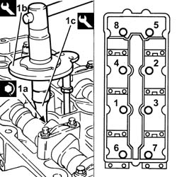
1. Tighten the nuts (1a) fixing the left cylinder head to the recommended torque using the angular tightening tools (1b) and (1c).
Lubricate the threads, nuts and washers with engine oil.
Follow the order shown in the diagram for each tightening sequence.
| Fastening | Component | Ø | Value (daNm) | |
|---|---|---|---|---|
| 1a | Nut | CYLINDER HEAD | M12 | (Engine crankcase side) 2.4 ÷ 2.6 + 228? ÷ 232? |
| Name | Country | |
|---|---|---|
| 1b | Protractor | 1.860.942.000 |
| Name | Country | |
|---|---|---|
| 1c | Spanner | 1.822.121.000 |
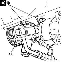
1. Place the power assisted steering pump (1a) complete with pipes back in its housing and fix it tightening the bolts (1b) to the recommended torque.
| Fastening | Component | Ø | Value (daNm) | |
|---|---|---|---|---|
| 1b | Bolt | POWER STEERING PUMP | M8 | (Support side) 2.3 ÷ 2.8 |
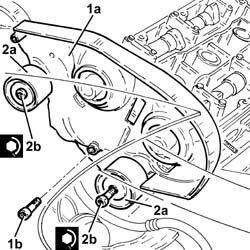
1. Fit the left rear protective timing gear cover (1a) and secure using the bolts (1b).
2. Place the timing belt fixed tensioners (2a) back in their housings and secure them tightening the bolts (2b) to the recommended torque.
| Fastening | Component | Ø | Value (daNm) | |
|---|---|---|---|---|
| 2b | Bolt | FIXED TENSIONER | M10 | (Cylinder head side) 4.5 ÷ 5.5 |
Place the left head toothed driven pulleys back in their housings and fasten them without tightening the bolts.
Place the fuel pipe, complete with injectors, back in its housing and fix it using the bolts.
Connect the electrical connections to the injectors.
Connect the quick-release connector for the front fuel supply pipe, fuel pipe side.
Place the intake manifolds complete with gaskets back in their housings and fasten them using the bolts.
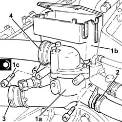
1. Place the thermostat (1a) complete with electrical connections box (1b) back in its housing and secure it tightening the bolts (1c) to the recommended torque.
| Fastening | Component | Ø | Value (daNm) | |
|---|---|---|---|---|
| 1c | Bolt | THERMOSTAT | M6 | (Cylinder head side) 0.8 ÷ 1.0 |
2. Connect the engine coolant return pipe from the climate control system heater, thermostat side, and tighten the band.
3. Connect the lower coolant outlet hose from the radiator, thermostat side, and tighten the band.
4. Connect the upper coolant inlet hose to the radiator, thermostat side, and tighten the band.
Connect the electrical connection to the engine coolant temperature sensor.
Connect the electrical connection for the knock sensor flywheel side.
Connect the electrical connection for the cam angle sensor.
Connect the electrical connection for the rpm sensor.
Connect the electrical connection for the right upper Lambda sensor.
Close the electrical connections box cover.
Connect the electrical connection to the air conditioning compressor electromagnet coupling.
Proceed with refitting
Op. 1080B38 LEFT CATALYTIC PRECONVERTER R R OR REPLACE CYLINDER HEAD GASKET.
Proceed with refitting
Op. 1076A70 HEAT SHIELD FOR LEFT CATALYTIC PRECONVERTER R R.
Proceed with refitting
Op. 1080B92 LEFT UPPER LAMBDA SENSOR R R.
Proceed with refitting
Op. 1088B20 ENGINE COOLING RADIATOR - R + R.
Proceed with refitting
- 7210A15 R.R. HEADLAMP HOUSING/FRONT WING CROSSMEMBER
Proceed with refitting
Op. 7025A34 BONNET LID LOCK (ONE) - R+R OR REPAIR.
Proceed with the refitting
Op. 5540B76 FRONT LIGHT CLUSTER WITH FOGLAMP ONE LH OR RH R R WITH INTERFERING PARTS REMOVED
(Right and left sides).
Proceed with refitting
Op. 7210E10 R.R. FRONT BUMPER.
Proceed with refitting
Op. 7055B42 LH OR RH REFLECTOR(ONE) ON REAR BUMPERS - R R.
Proceed with refitting
Op. 1048A10 AIR CLEANER FILTERING ELEMENT - REPLACE.
Proceed with refitting
Op. 5530B52 BATTERY DRIP TRAY/SUPPORT - R.R..
Proceed with refitting
Proceed with refitting
Op. 1048A48 THROTTLE HEATER SLEEVE - R R.
Proceed with refitting
Op. 1032B10 TOOTHED TIMING BELT - R + R FOR TIMING ADJUSTMENT OR REPLACEMENT.
Proceed with refitting
Op. 1016A34 RIGHT-HAND CAM COVER - R + R AND REPLACE GASKET.
Proceed with refitting
Op. 5510C18 RIGHT HAND CYLINDER HEAD IGNITION COIL - R+R.
Proceed with refitting
Op. 1072B50 SLEEVES CONNECTING AIR CAPACITY BOX TO INLET MANIFOLD IS - R+R.
Proceed with refitting
Op. 1016A30 LEFT CAM COVER - R + R AND REPLACE GASKET.
Proceed with refitting
Op. 5510C16 LEFT HAND CYLINDER HEAD IGNITION COIL - R+R.
Proceed with refitting
Op. 1016A42 LEFT HAND CYLINDER HEAD IGNITION COIL COVER - R+R.
Proceed with refitting
Op. 1032D12 TIMING SYSTEM PROTECTIVE COVER(S) - R + R.
Proceed with refitting
Op. 1092A10 CRANKSHAFT SERVICES PULLEY - R.R..
Proceed with refitting
Op. 1092G10 SINGLE ENGINE BELT R R.
Proceed with refitting
Op. 7055B64 LH OR RH REFLECTOR(ONE) ON REAR BUMPERS - R R.
Proceed with refitting
Op. 4450B04 RIGHT FRONT WHEEL R R.
Refill the engine cooling system
Op. 0010T20 COOLANT CHECK DENSITY AND TOP UP IF NECESSARY.
Refill the air conditioner refrigerant system
Op. 5040A10 EXPANSION/CONNECTION PIPE - R R.
Proceed with refitting
Op. 7055B54 UNDER-ENGINE GUARD - R R.
Connect the negative (-) battery terminal.
Remove the car from the ramps.
Parts & tools for this job Staging For 2003 Alfa Romeo GT
- PARTEngine gasket setSearch: Alfa Romeo GT 2003 engine gasket set
- TOOLTorque wrenchSearch: 3/8 inch torque wrench
- TOOLFeeler gauge setSearch: feeler gauge set
Links open Amazon search results in a new tab. As an Amazon Associate I earn from qualifying purchases.