
SYSTEM COMPONENTS DESCRIPTION (page 8 of 11)
- Make
- Land Rover
- Model
- Range Rover P38
- Section
- DESCRIPTION AND OPERATION
SUPPLEMENTARY RESTRAINT SYSTEM
13
DESCRIPTION AND OPERATION
The front passenger airbag module is mounted to the
fascia by way of four bolts. A link lead connects the
module to the fascia harness, with a red multiplug
connector located on the bracket behind the glove
box.
When an activation signal is received by the
passenger airbag squib, the activated igniter produces
heat causing the gas pellets to generate nitrogen gas
which fills the airbag. The force of the inflating airbag
breaks the specially weakened break lines in the
polyurethane cover. Once free of the module, the
nylon bag inflates to its full extent to provide a
protective cushion between the front seat passenger
and the fascia / windscreen.
When the bag is fully inflated, vents in the airbag
prevent further pressure build-up so that progressive
deceleration is provided as the occupant contacts the
cushion.
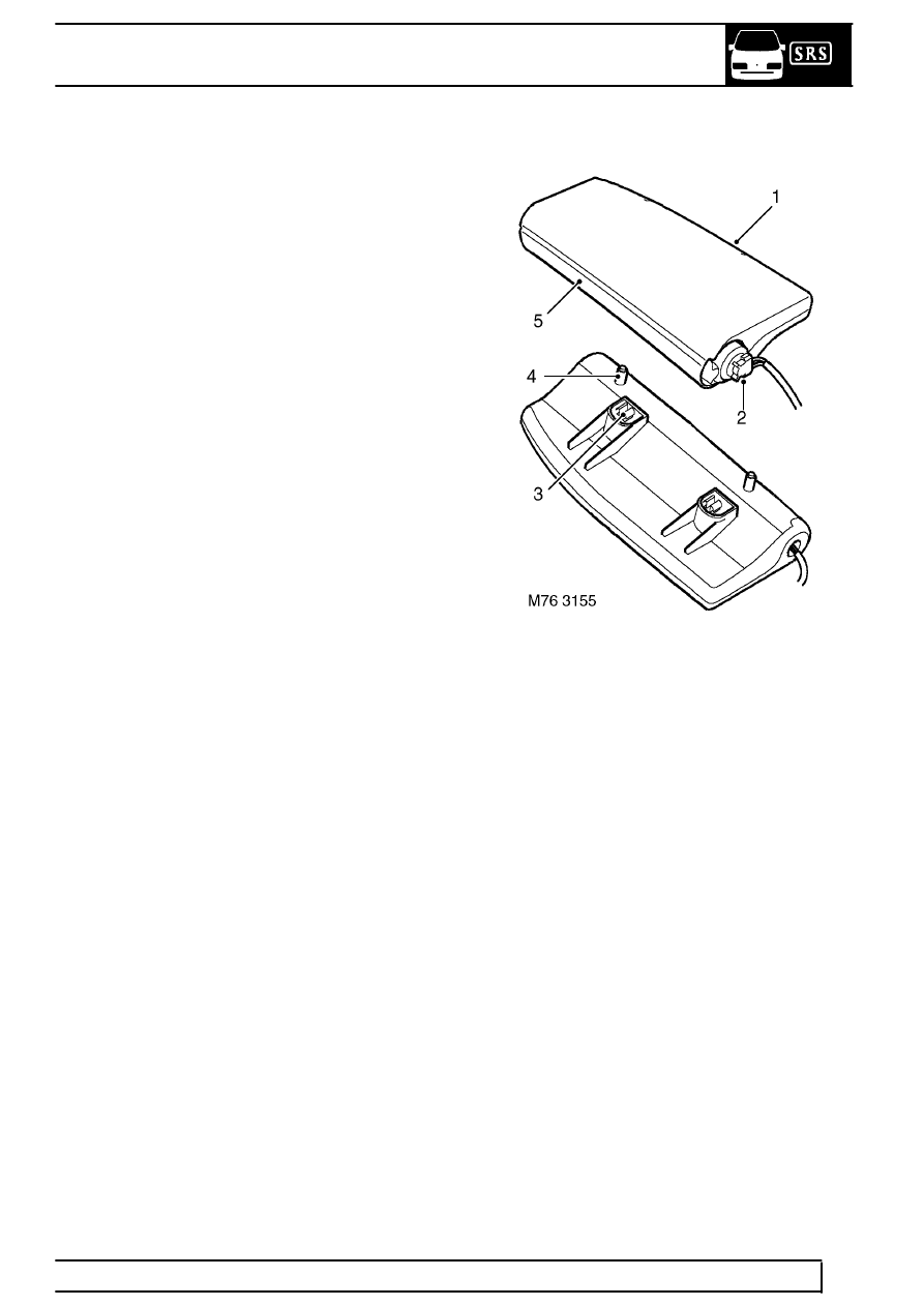
Side airbag modules
1. Module front edge (airbag emergence point)
2. Electrical connector (non-removable)
3. Location lugs
4. Fixing studs
5. Module hinge
The driver and passenger side airbags are mounted to
the squab seat frame. The modules are handed (i.e. a
right hand module must be fitted to a RH seat and a
left hand module must be fitted to a LH seat). The side
airbags are activated by a control signal from the SRS
DCU in the event of a side impact or a front angled
impact of sufficient severity to cause both front and
side airbag deployment.
The side airbag module is a moulded plastic case
which houses a folded nylon fabric bag, the gas
generant capsules and an igniter squib. The rear of
the side airbag module features two studs which are
used for mounting the module to the seat frame and
are secured in position by two Nylock nuts. The back
of the module also has moulded plastic location lugs,
which are offset to ensure that only the correct
handed module is fitted to the relevant seat.
Parts & tools for this job Staging For Land Rover Range Rover
- TOOLOBD2 scanner with SRSSearch: OBD2 scanner ABS SRS
- TOOLTrim removal tool kitSearch: trim removal tool kit
Links open Amazon search results in a new tab. As an Amazon Associate I earn from qualifying purchases.