
75 - SUPPLEMENTARY RESTRAINT SYSTEM: DESCRIPTION AND OPERATION (page 3 of 4)
- Make
- Land Rover
- Model
- Range Rover P38
SUPPLEMENTARY RESTRAINT SYSTEM
19
DESCRIPTION AND OPERATION
SRS warning lamps and system diagnostics
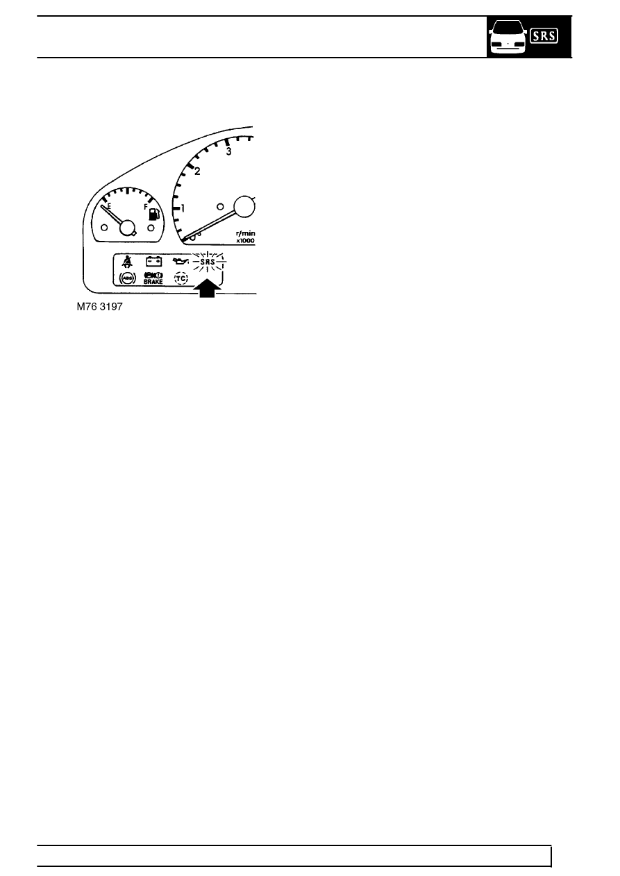
The SRS warning lamp is located in the instrument
pack and has two bulbs behind the SRS warning lamp
window. If either of the bulbs fail, the DCU will
illuminate the other bulb permanently to indicate that a
system fault is present (i.e. warning lamp bulb failure).
The SRS warning lamp illuminates after the ignition
switch has been turned to position ’II’ in order to
provide a lamp check. After about 5 seconds, the
warning lamp will go out for the remainder of the
ignition cycle, providing the SRS system integrity is
maintained. The system checks the condition of the
SRS DCU, crash sensors and the SRS harnesses.
If one of the following faults are experienced when the
ignition switch is turned to position ’II’, the SRS
warning lamp will illuminate and remain on for the
duration of the ignition cycle:
•
DCU connector not engaged or faulty
•
Harness fault
•
Earth connection fault
•
Fuse open circuit
If a system fault is detected whilst driving, the warning
lamp illuminates, to indicate that there is a fault with
the SRS system. With the warning lamp on, the SRS
system may not operate in the event of a collision.
While the ignition is on, the diagnostic function of the
SRS DCU monitors the SRS system for faults. If a
fault is detected, the DCU stores a related fault code
in non-volatile memory and switches the earth output
to illuminate the SRS warning lamp. A maximum of
five faults can be stored in memory along with the
timing information associated with each fault. The fault
memory is accessible through the use of testbook and
the K-line communications bus.
With a supply voltage range fault the warning lamp is
illuminated, once the correct system voltage returns
within range the lamp will extinguish. The warning
lamp will remain lit for a minimum of 5 seconds. With
all other faults including intermittent faults, the warning
lamp is illuminated for the remainder of the drive
cycle. The SRS warning lamp will not illuminate on the
next ignition cycle unless the fault re-occurs, but the
fault code remains stored in memory.
For a permanent fault, the SRS lamp will stay on after
the initial warning lamp test and latch on for every
ignition cycle until the cause of the fault has been
resolved. In addition, the diagnostic system will record
an ’AIR BAG FAULT’.
After detecting a fault, the system may retain some
operational capability:
•
If a fault is detected in a SRS circuit, only that
particular circuit is disabled; the other airbag and
pre-tensioner circuits remain operational and will
still be deployed in the event of a collision.
•
If an internal DCU or power supply fault is
detected, the complete system will be disabled.
•
If a fault exists in the SRS warning lamp circuit,
the lamp will not illuminate during the lamp
check at ignition on, but provided there are no
other faults, the system will remain fully
operational.
Additional information that can be accessed using
’Testbook’ via the diagnostics socket include:
•
SRS DCU code number
•
Evolution number of the hardware, software and
diagnostic protocol
•
Status of the crashed lock mode
•
Vehicle identification number (VIN) data
The SRS DCU logs the fault in internal memory, this
can be accessed using TestBook via the diagnostic
socket located on the passenger side fascia closing
panel.
Parts & tools for this job Staging For Land Rover Range Rover
- TOOLOBD2 scanner with SRSSearch: OBD2 scanner ABS SRS
- TOOLTrim removal tool kitSearch: trim removal tool kit
Links open Amazon search results in a new tab. As an Amazon Associate I earn from qualifying purchases.