
60 - FRONT SUSPENSION - ELECTRONIC AIR SUSPENSION (SYSTEM OPERATION): DESCRIPTION AND OPERATION
- Make
- Land Rover
- Model
- Range Rover P38
- Section
- DESCRIPTION AND OPERATION › SYSTEM OPERATION
ELECTRONIC AIR SUSPENSION
7
DESCRIPTION AND OPERATION
SYSTEM OPERATION
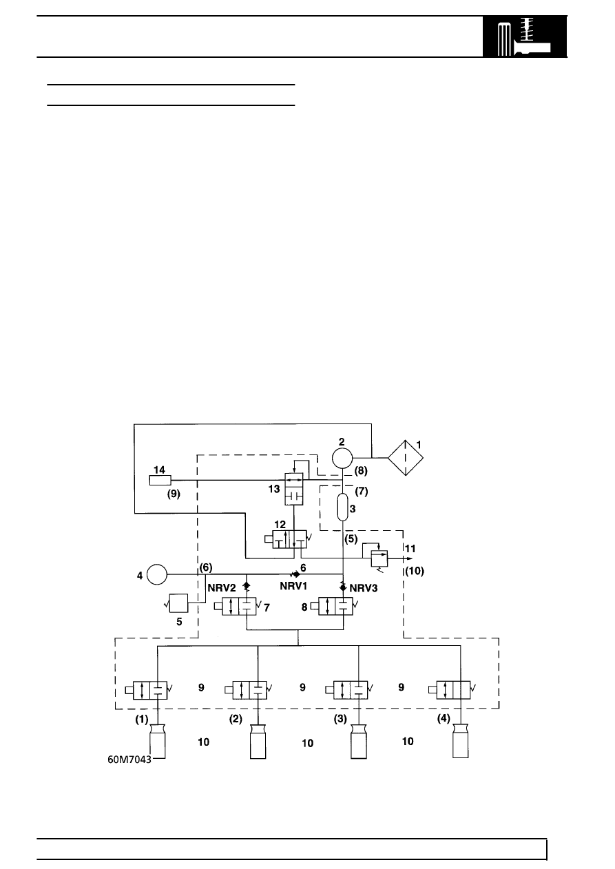
Numbers refer to pneumatic circuit diagram
Air is drawn through the inlet filter (1) to the
compressor (2), where it is compressed to 10
±
0,5
bar (145
±
7.25 lbf/in
2
).
Compressed air passes to the air dryer (3) where
moisture is removed as it flows through the dryer
dessicant. The dessicant in the lower portion of the
dryer becomes wet.
Dried air passes through a non-return valve NRV1 to
the reservoir (4).
The 3 non-return valves (6) ensure correct air flow.
They also prevent loss of spring pressure if total loss
of reservoir pressure occurs.
The pressure switch (5) maintains system pressure
between set limits by switching on and off the
compressor via an ECU controlled relay.
For air to be admitted to an air spring (10), the inlet
valve (7) must be energised together with the relevant
air spring solenoid valve (9).
For air to be exhausted from an air spring, the exhaust
valve (8) must be energised together with the relevant
air spring solenoid valve.
The solenoid diaphragm valve (12) ensures that all air
exhausted to atmosphere passses through the dryer.
Exhausted air passes vertically downwards through
the dryer. This action purges moisture from the
dessicant and regenerates the air dryer.
Air is finally exhausted through the system air
operated diaphragm valve (13) and to atmosphere
through a silencer (14) mounted below the valve
block.
Parts & tools for this job Staging For Land Rover Range Rover
- TOOLCoil spring compressorSearch: coil spring compressor
- TOOLBall joint separatorSearch: ball joint separator
- PARTFront shock absorbersSearch: Land Rover Range Rover front shock absorbers
Links open Amazon search results in a new tab. As an Amazon Associate I earn from qualifying purchases.