
57 - STEERING: DESCRIPTION AND OPERATION (page 2 of 4)
- Make
- Land Rover
- Model
- Range Rover P38
57
STEERING
NEW RANGE ROVER
4
DESCRIPTION AND OPERATION
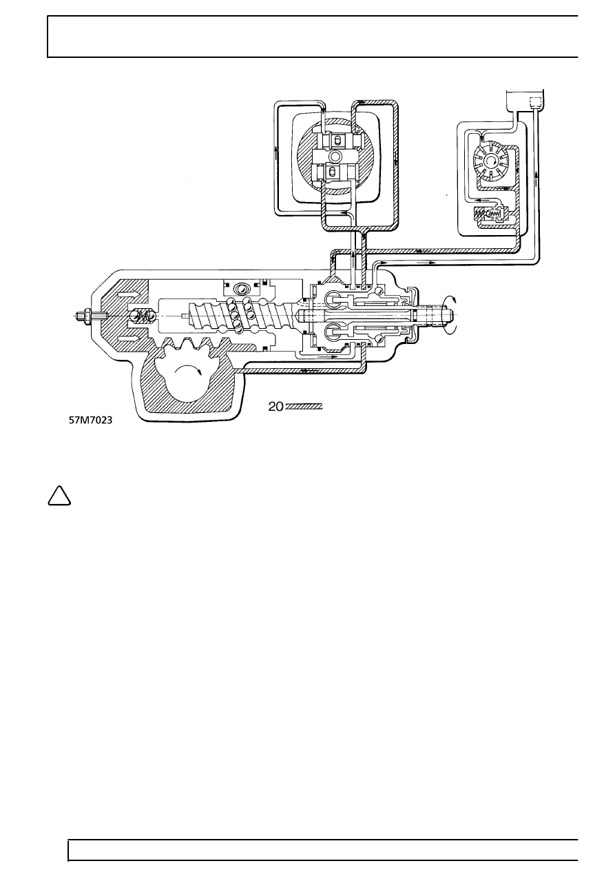
20. Hydraulic flow steering wheel turned clockwise
NOTE: The illustrations show a sectional
view of the steering box with a section
through the valve spools directly above to
demonstrate valve spool movement and fluid flow.
Illustration 57M7022 shows steering wheel in the
straight ahead position, valve spools in the neutral
position.
Illustration 57M7023 shows hydraulic flow when
steering wheel is turned clockwise.
The steering housing (1) contains a complete
mechanical steering gear box and the steering control
valve. It also forms the power cylinder.
Steering wheel rotation is converted into axial
movement of the piston (2) by a chain of balls (5)
running in the worm (4). When the worm is rotated,
the balls enter the recirculating tube (6) and pass to
the other end to form an endless chain. The sector
shaft (3), which is at right angles to the piston axis, is
rotated by meshing teeth. The steering drop arm,
fitted to the sector shaft, transmits steering movement
via the steering linkage to the road wheels.
The worm is connected to the input shaft (9) by the
torsion bar (10). The worm head contains two valve
spools (11 and 12), which are at right angles to the
axis of the worm. Two pins on the input shaft engage,
without play, in the valve spools. When the steering
wheel is turned, there is relative rotation between the
input shaft and the worm which is made possible by
the torsion bar. The valve spools follow the movement
of the steering column, when the torsion bar twists the
pistons are moved from the neutral position into their
working position. When the steering wheel is
released, the torsion bar and the valve pistons return
to the neutral position. The force required at the
steering wheel to overcome the torsion bar and
therefore move the valves from the neutral position
provides the driver with good steering feel.
Parts & tools for this job Staging For Land Rover Range Rover
- TOOLTie rod end toolSearch: tie rod end puller
- TOOLBall joint separatorSearch: ball joint separator
- FLUIDPower steering fluidSearch: Land Rover power steering fluid
Links open Amazon search results in a new tab. As an Amazon Associate I earn from qualifying purchases.