
17 - EMISSION CONTROL: DESCRIPTION AND OPERATION (page 2 of 6)
- Make
- Land Rover
- Model
- Range Rover P38
17
EMISSION CONTROL
NEW RANGE ROVER
32
DESCRIPTION AND OPERATION
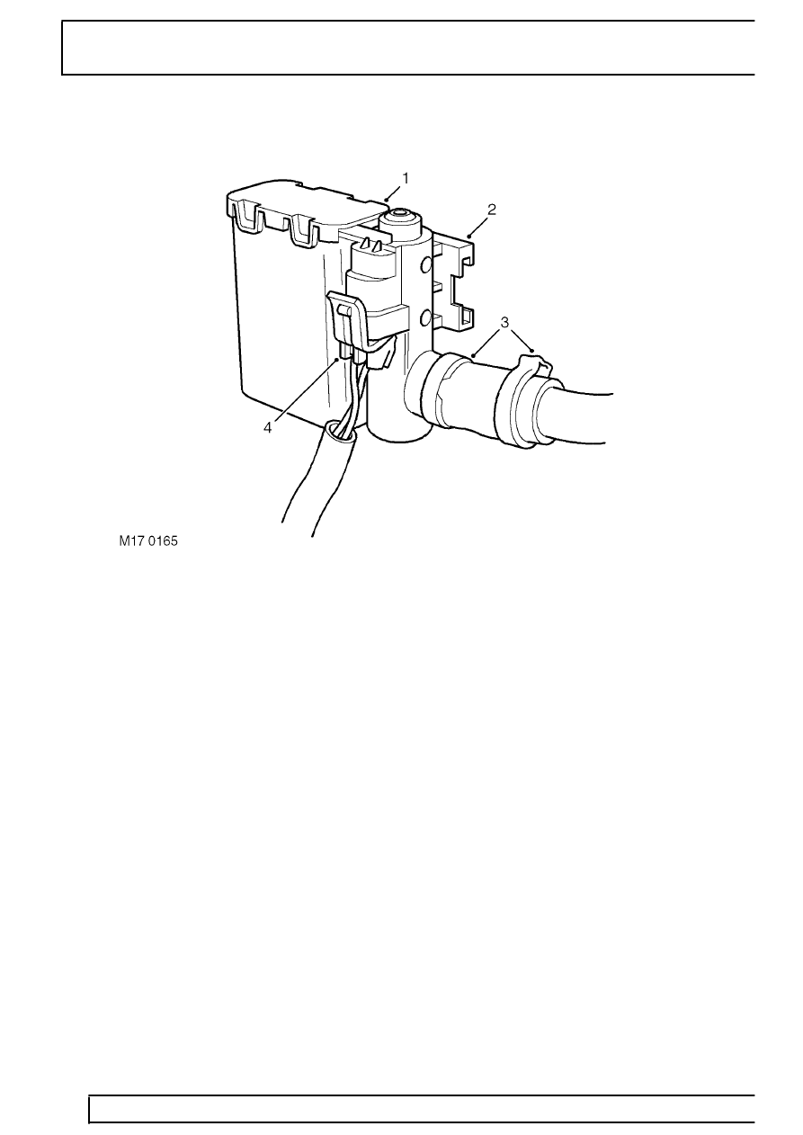
Canister Vent Solenoid (CVS) unit - (NAS only)
1. CVS unit
2. Mounting bracket
3. Spring clips to pipe from EVAP canister
4. Harness connector
The CVS unit is mounted at the rear right hand side of
the engine bay on a slide-on bracket. The vent pipe
from the EVAP canister is connected to a stub pipe on
the CVS unit via a short rubber hose. The rubber hose
is connected to the CVS unit and plastic pipe by two
metal band clips. A two-pin connector links to the
engine management ECM via the engine harness for
solenoid control. One wire is for the voltage feed, the
other is the valve drive line to the ECM. The solenoid
is operated when the ECM grounds the circuit.
The valve is normally open, allowing any build up of
air pressure within the evaporation system to escape,
whilst retaining the environmentally harmful
hydrocarbons in the EVAP canister.
When the ECM is required to run a fuel evaporation
system test, the CVS valve is energised and closes to
seal the system. The ECM is then able to measure the
pressure in the EVAP system using the fuel tank
pressure sensor. The ECM performs electrical
integrity checks on the CVS valve to determine wiring
or power supply faults. The ECM can also detect a
valve blockage if the signal from the fuel tank
pressure sensor indicates a depressurising fuel tank
while the CVS valve should be open to atmosphere.
The following failure modes are possible:
•
Connector or wiring harness fault (open or short
circuit)
•
Valve stuck open or shut
•
Valve blocked
Parts & tools for this job Staging For Land Rover Range Rover
- PARTExhaust gasketSearch: Land Rover Range Rover exhaust gasket
- TOOLPenetrating oilSearch: penetrating oil
- TOOLOBD2 scannerSearch: OBD2 scanner
Links open Amazon search results in a new tab. As an Amazon Associate I earn from qualifying purchases.