
SRS Control Diagram
- Make
- Land Rover
- Model
- Range Rover L322 Range Rover System Description and Operation
- Section
- SRS Control Diagram
RESTRAINT SYSTEMSSRS Control Diagram · page 1 of 2
RESTRAINT SYSTEMS
75-18
DESCRIPTION AND OPERATION
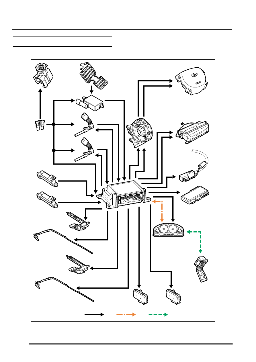
SRS Control Diagram
A = Hardwired connection; B = K bus; C = Diagnostic DS2 bus
M76 4464A
1
2
3
4
5
6
7
8
9
10
11
12
13
14
15
16
17
18
19
20
21
22
A
B
C
Parts & tools for this job Staging For Land Rover Range Rover
- TOOLOBD2 scanner with SRSSearch: OBD2 scanner ABS SRS
- TOOLTrim removal tool kitSearch: trim removal tool kit
Links open Amazon search results in a new tab. As an Amazon Associate I earn from qualifying purchases.