
Light Check Module (LCM) (page 2 of 5)
- Make
- Land Rover
- Model
- Range Rover L322 Range Rover System Description and Operation
- Section
- Description
LIGHTING
DESCRIPTION AND OPERATION
86-2-9
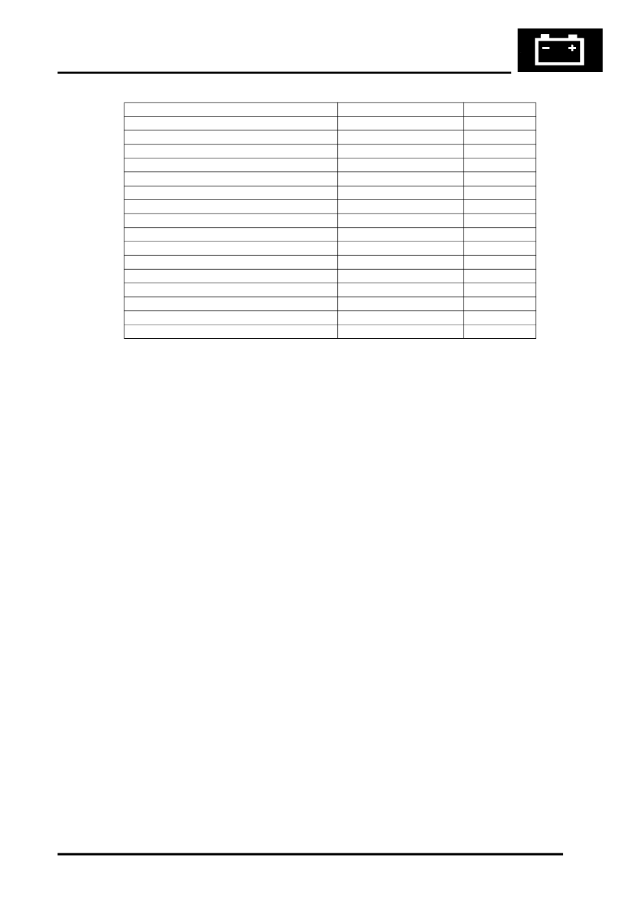
Exterior Bulb Type/Rating Table
The bulbs are driven by MOSFETS within the LCM. The LCM provides a Pulse Width Modulation (PWM) output to
the front parking lamp and the tail lamp bulbs to protect the bulbs. The PWM output is rapidly switched on and off to
provide bulb emulation when a bulb fails.
Input Signals for Lamp Control
The LCM receives inputs from the following switches:
l
Lighting switch for side lamps and headlamps
l
Momentary push switches for front and rear fog lamps
l
Steering column switch for direction indicators and main beam/headlamp flash
l
Brake switch
l
Momentary push switch for hazard warning.
The switches are supplied with a 10mA supply from the LCM and switch to ground when operated. The LCM detects
that a switch has been operated (ON) when its closing resistance is less than 100
Ω
and is detected as OFF when its
resistance is more than 10K
Ω
.
The LCM also receives ignition switch status via hardwired connections and also on the I and K Bus via the instrument
pack.
A reverse gear engaged signal is also received on the I and K bus systems to enable the LCM to activate the reverse
lamps. The trailer module also outputs a signal to inform the LCM that a trailer is or is not connected. If a trailer is
connected, the LCM transfers control of the trailer reverse lamps and the rear fog lamp to the trailer module.
Via the bus systems the LCM receives a hazard warning lamp activation message from the DCU, via the BCU, in the
event of a crash or from the BCU if the alarm system is triggered.
Bulb
Type
Rating
Halogen headlamps – Dip beam
Halogen H7U
55W
Bi-xenon headlamps – Dip beam
Xenon DS2
35W
Headlamps – Main beam
Halogen H7U
55W
Front fog lamps
Halogen H7U
55W
Rear fog lamps
Bayonet
21W
Direction indicators – front
Bayonet
21W
Direction indicators – side repeater
Capless
5W
Direction indicators – rear
Bayonet
21W
Side lamps – front
Bayonet
5W
Tail lamps
Bayonet (Twin filament)
21W/5W
Brake lamps
19 LED's
–
Centre High Mounted Stop Lamp (CHMSL)
20 LED's
–
Number plate lamps
Festoon
5W
Reverse Lamps
Bayonet
6W
Front side marker lamp (NAS only)
Capless
5W
Rear side marker lamp (NAS only)
Capless
5W
Parts & tools for this job Staging For Land Rover Range Rover
- TOOLOBD2 scannerSearch: OBD2 scanner
- TOOLDigital multimeterSearch: automotive digital multimeter
- TOOLBack-probe test leadsSearch: back probe test leads
Links open Amazon search results in a new tab. As an Amazon Associate I earn from qualifying purchases.