
Liquid Crystal Display (LCD)
- Make
- Land Rover
- Model
- Range Rover L322 Range Rover System Description and Operation
- Section
- Description › Liquid Crystal Display (LCD)
INSTRUMENTS
DESCRIPTION AND OPERATION
88-9
The instrument pack is connected via two wires to the Engine Coolant Temperature (ECT) sensor. This sensor has a
four pin connector, with the remaining two pins connected to the ECM. The ECT sensor is an NTC sensor located in
the engine coolant flow. The instrument pack outputs a signal voltage to the sensor and measures the returned signal.
The sensor resistance falls as the coolant temperature increases. The instrument pack microprocessor evaluates the
returned signal and converts the information into an output drive to position the temperature gauge needle at the
appropriate position. The engine coolant temperature is available for use by other vehicle systems via the CAN.
ENGINE MANAGEMENT SYSTEM – Td6, DESCRIPTION AND OPERATION, Description.
ENGINE MANAGEMENT SYSTEM – V8, DESCRIPTION AND OPERATION, Bosch ME 7.2 Engine
The following table shows coolant temperature relationship to gauge needle pointer position.
The engine coolant temperature gauge is the same on all pack variants. The gauge display has a blue segment for
low temperatures and a red segment for excessively high temperatures. For normal engine operating temperatures
the gauge needle pointer is positioned centrally in the gauge display zone.
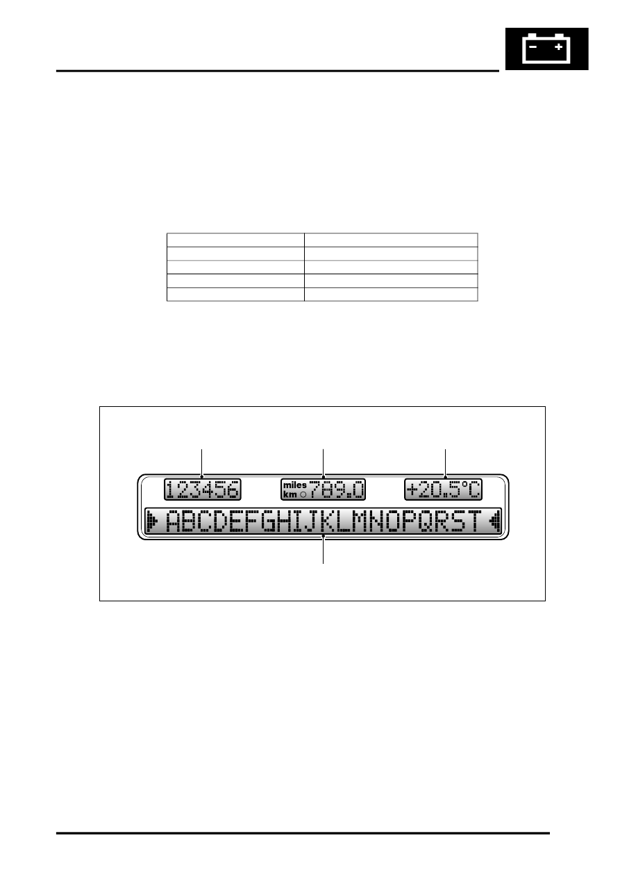
Liquid Crystal Display (LCD)
1 Total distance odometer
2 Trip meter
3 Ambient temperature display
4 Message centre
The instrument pack has four separate LCD's which show the following data:
l
Odometer – Displays the total vehicle distance travelled
l
Trip meter – Displays the total vehicle distance travelled since last reset
l
Ambient temperature – Displays the external ambient temperature in
°
C or
°
F
l
Message centre – Displays system information to the driver.
The LCD is an integral part of the instrument pack. The LCD comprises black segments on a grey background or
green illuminated when the light switch is on. The LCD is illuminated by backlighting which is provided by five 12V/
1.5W single filament bulbs.
Coolant Temperature
Gauge Needle Pointer Position
15.00
°
C (59.00
°
F)
At beginning of blue segment
50.25
°
C (122.45
°
F)
At end of blue segment
95.25
°
C (203.45
°
F)
At centre of display
126.00
°
C (258.80
°
F)
At centre of red segment
M88 0345
4
1
2
3
Parts & tools for this job Staging For Land Rover Range Rover
- TOOLTorque wrenchSearch: 3/8 inch torque wrench
- TOOLSocket setSearch: socket set metric
- BOOKHaynes manualSearch: Haynes manual Land Rover Range Rover
Links open Amazon search results in a new tab. As an Amazon Associate I earn from qualifying purchases.