
Cylinder Block Components (page 3 of 10)
- Make
- Land Rover
- Model
- Range Rover L322 Range Rover System Description and Operation
- Section
- Description
ENGINE - V8
12-2-4
DESCRIPTION AND OPERATION
Crankcase Ventilation
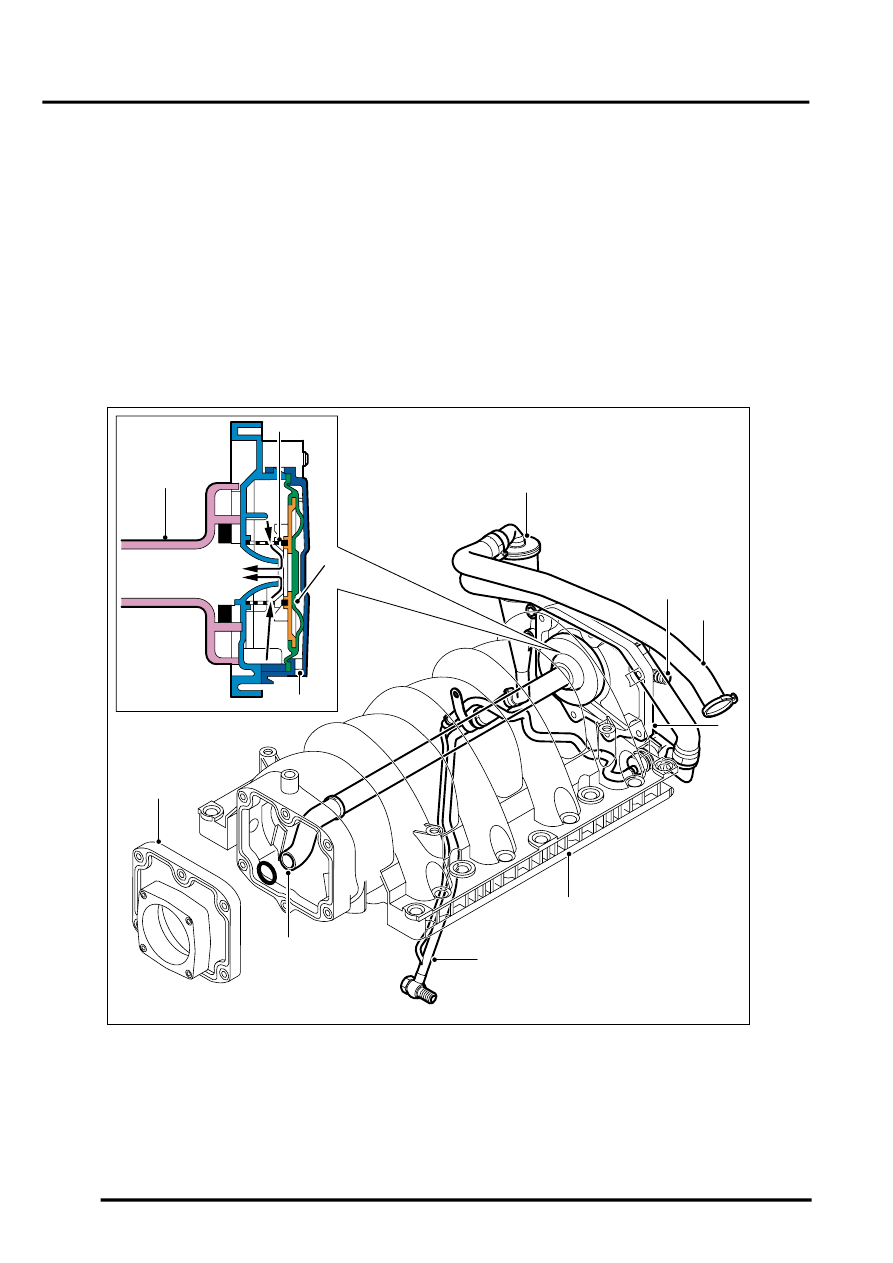
The crankcase ventilation system is pressure regulated by a valve mounted at the rear of the inlet manifold. Vacuum
supply ports are incorporated on the valve for the power brake booster and the fuel pressure regulator
The pressure regulating vent valve varies the vacuum applied to the crankcase depending on engine load. The valve
is balanced between spring pressure and the amount of manifold vacuum. At idle when the vacuum is high, the valve
closes down and only allows a small amount of blow-by vapours to pass into the manifold. At part to full load
conditions, the spring opens the valve and additional blow-by gasses flow into the manifold. An additional tube leads
the blow-by gasses through the manifold and up to the mixing plate.
The crankcase ventilation system is completely sealed. Hose clamps are used at all connections to ensure that the
system does not contain any leaks.
The crankcase ventilation system uses a cyclone separator to purge the blow-by gasses of any oil vapours. The oil
vapours condense in the separator and drain back into the sump.
Crankcase Ventilation System
1 Oil separator
2 Breather hose, oil separator to vent valve
3 Breather hose, LH camshaft cover to oil
separator
4 Inlet manifold cover and vent valve
5 Inlet manifold
6 Oil drain pipe assembly
7 Inlet manifold vacuum pipe
8 Mixing plate
9 Vent valve spring
10 Vent valve diaphragm
11 Atmospheric vent
12 Blow-by gasses
M12 7839A
1
2
3
4
5
6
10
7
9
12
11
7
8
Parts & tools for this job Staging For Land Rover Range Rover
- PARTEngine gasket setSearch: Land Rover Range Rover engine gasket set
- TOOLTorque wrenchSearch: 3/8 inch torque wrench
- TOOLFeeler gauge setSearch: feeler gauge set
Links open Amazon search results in a new tab. As an Amazon Associate I earn from qualifying purchases.