
Parking Switch
- Make
- Land Rover
- Model
- Range Rover L322 Range Rover System Description and Operation
- Section
- Description › Parking Switch
DRIVING AIDS
DESCRIPTION AND OPERATION 86-10-5
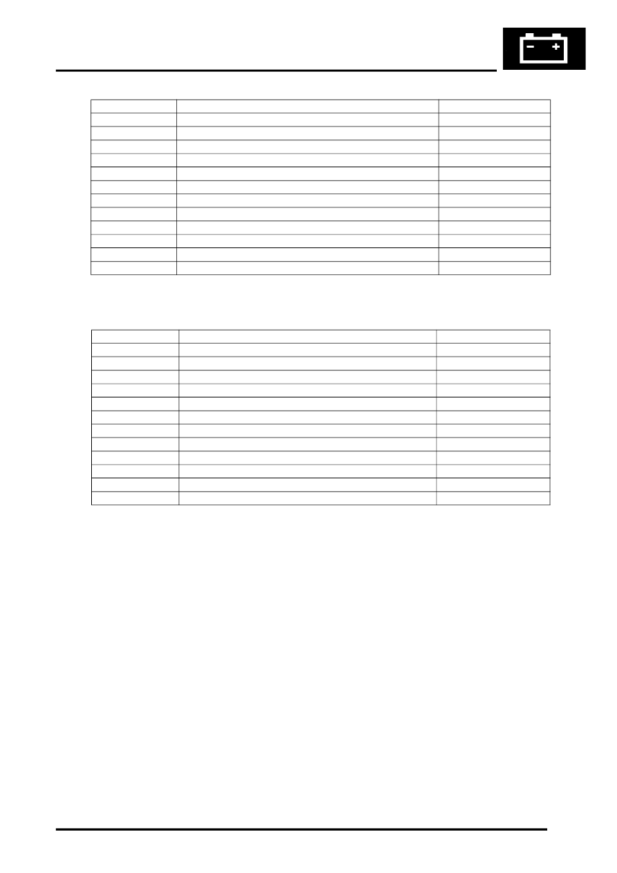
PDC ECU Harness Connector C0958 Pin Details
PDC ECU Harness Connector C1457 Pin Details
PDC Sounder
The PDC sounder produces the audible warnings with which the PDC ECU informs the driver of system status and
objects detected at the rear of the vehicle. The PDC sounder is installed behind the trim in the RH side of the luggage
compartment, on the underside of the shelf.
The chime produced on the PDC sounder has a lower tone than that produced on the instrument pack sounder (which
is used to warn of objects detected at the front of the vehicle), to enable the driver to differentiate between the two.
Parking Switch
The parking switch is a non latching push switch installed on the centre console for selecting the system on and off.
When pressed, the switch connects a ground to the PDC ECU. An orange LED above the switch indicates when the
PDC system is active. The LED is activated by a power feed from the PDC ECU.
Pin No.
Description
Input/Output
1
Rear LH inner PDC sensor ground
–
2
Rear RH outer PDC sensor ground
–
3
Rear LH outer PDC sensor ground
–
4
Rear RH inner PDC sensor supply
Output
5
Rear LH inner PDC sensor supply
Output
6
Rear RH outer PDC sensor supply
Output
7
Rear RH inner PDC sensor supply
Output
8
Rear RH inner PDC sensor signal
Input
9
Rear LH inner PDC sensor signal
Input
10
Rear RH outer PDC sensor signal
Input
11
Rear LH outer PDC sensor signal
Input
12
Rear LH outer PDC sensor supply
Output
Pin No.
Description
Input/Output
1
Front LH inner PDC sensor ground
–
2
Front RH outer PDC sensor ground
–
3
Front LH outer PDC sensor ground
–
4
Front RH inner PDC sensor supply
Output
5
Front LH inner PDC sensor supply
Output
6
Front RH outer PDC sensor supply
Output
7
Front RH inner PDC sensor ground
–
8
Front RH inner PDC sensor signal
Input
9
Front LH inner PDC sensor signal
Input
10
Front RH outer PDC sensor signal
Input
11
Front LH outer PDC sensor signal
Input
12
Front LH outer PDC sensor supply
Output
Parts & tools for this job Staging For Land Rover Range Rover
- TOOLOBD2 scannerSearch: OBD2 scanner
- TOOLDigital multimeterSearch: automotive digital multimeter
- TOOLBack-probe test leadsSearch: back probe test leads
Links open Amazon search results in a new tab. As an Amazon Associate I earn from qualifying purchases.