
Supplementary restraint system precautions (page 7 of 7)
- Make
- Land Rover
- Model
- Freelander Service Procedures
GENERAL INFORMATION
03-26
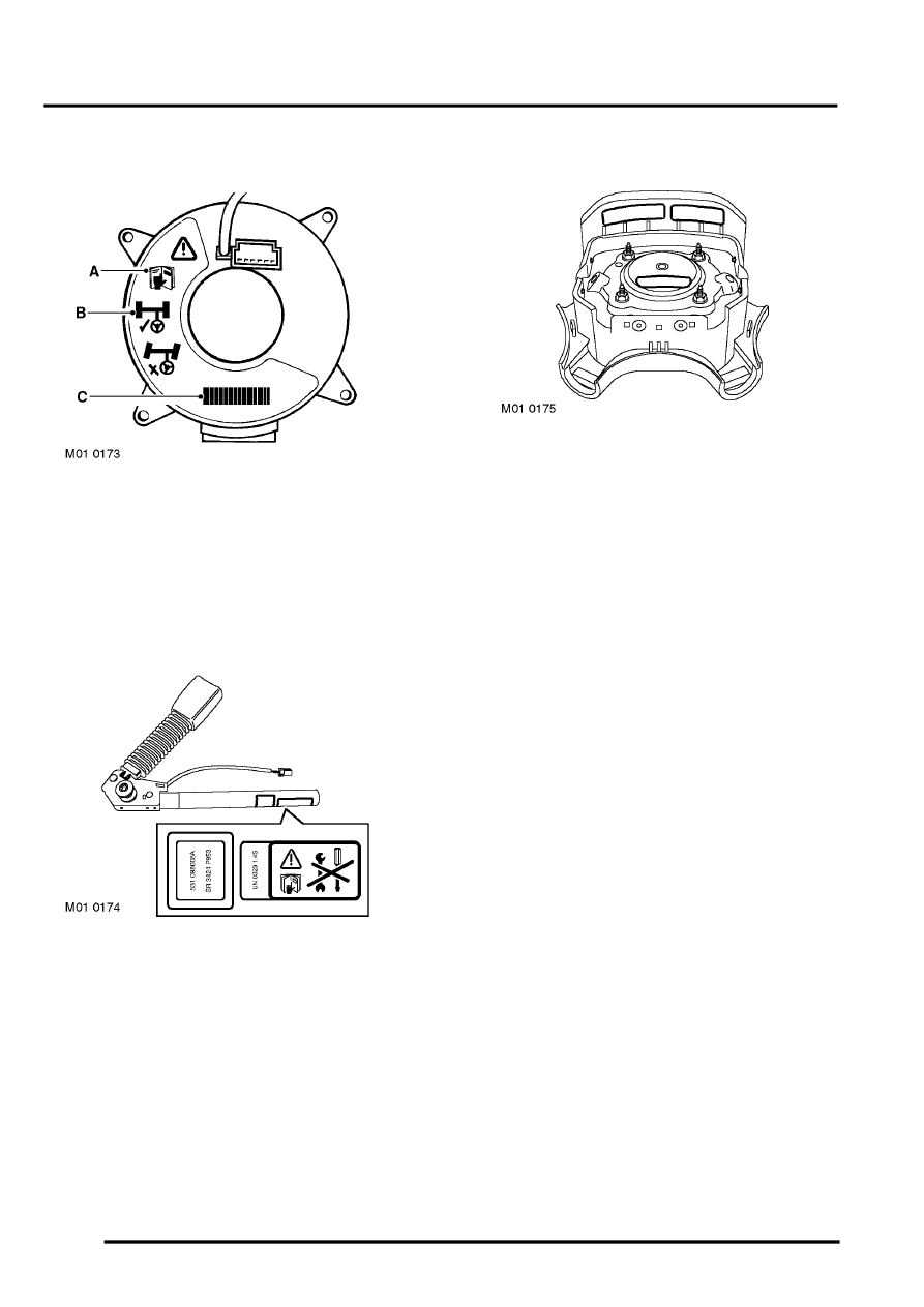
Rotary coupler
A - Refer to the Workshop Manual for detailed
instructions.B - Ensure wheels are in the straight
ahead position before removal and refitting.C -
LAND ROVER Part Number/Bar code - The code
must be recorded and quoted for ordering purposes.
Front seat belt pre-tensioners
A warning label is fixed to the piston tube of the front
seat belt pre-tensioners:
l
Exercise caution.
l
Refer to the publication where the procedures,
instructions and advice can be found (usually
Workshop Manual or Owner's Handbook) for
working on SRS system components.
l
Do not attempt to repair or disassemble.
Bar codes
Driver's airbag module
Bar codes are fitted to SRS system components and
components which are critically related to SRS
operation. The code number(s) must be recorded if
the component is to be replaced. Components
featuring bar codes include the following:
l
Driver's front airbag module – label attached to
rear of module housing.
l
Passenger front airbag module – label attached
to rear of module housing.
l
Rotary coupler – label attached on face of rotary
coupler.
l
DCU – included on label on top of DCU.
l
SRS wiring – label attached around harness
wires.
VEHICLE RECOVERY
Observe the following procedures for vehicle towing
after a collision has taken place:
Towing – SRS components not deployed
Normal towing procedures are unlikely to cause an
SRS module to deploy. However, as a precaution,
switch the ignition off and then disconnect both
battery leads. Disconnect the negative '-' lead first.
Towing – SRS components deployed
Once the driver's airbag has been deployed, the
vehicle must have a front suspended tow. However,
as a precaution, switch the ignition off and then
disconnect both battery leads. Disconnect the
negative '-' lead first.
Parts & tools for this job Staging For Land Rover Freelander
- TOOLOBD2 scanner with SRSSearch: OBD2 scanner ABS SRS
- TOOLTrim removal tool kitSearch: trim removal tool kit
Links open Amazon search results in a new tab. As an Amazon Associate I earn from qualifying purchases.