
Lower arm assembly
- Make
- Land Rover
- Model
- Freelander Service Procedures
- Section
- REPAIRS › Lower arm assembly
FRONT SUSPENSION
60-10
REPAIRS
Refit
1. Inspect damper, spring mounting rubbers and
bearing for deterioration and damage.
2. Clean mating faces of spring, mounting and
mounting plate.
3. Clean damper shaft and bump stop plate.
4. Position spring and damper assembly to spring
compressor. Compress spring.
5. Fit damper to spring, ensure spring locates in
cut recess in damper plate.
6. Fit bump cup, bump stop and dust cover to
damper.
7. Fit spring aid and bump plate.
8. Fit mounting plate and rebound washer.
9. Using new nut, hold damper shaft with Allen
key and tighten nut to 57 Nm (42 lbf.ft).
CAUTION: Note alignment of top mounting,
spring and damper dust cover.
10. Release and remove spring from compressor.
11. Clean mating face of top mounting plate.
12. Position damper assembly and align top
mounting to body, fit nuts and tighten to 45 Nm
(33 lbf.ft).
13. LH side: Position fusebox, fit nuts and tighten
to 8 Nm (6 lbf.ft).
14. LH side: Connect positive and negative leads,
fit bolts and tighten to 8 Nm (6 lbf.ft).
15. LH side: Connect multiplug to fusebox.
16. RH side: Position coolant reservoir and secure
with bolt.
17. Fit hub to damper, fit nuts and bolts and tighten
to 205 Nm (151 lbf.ft).
18. Clean anti-roll bar link taper and mating face.
19. Connect anti-roll bar link, fit new nut and tighten
to 55 Nm (41 lbf.ft).
CAUTION: Use a spanner and an Allen key
to prevent ball joint rotating when undoing
link.
20. Clean track rod taper and mating face.
21. Connect track rod end to steering arm using
new nut and tighten nut to 55 Nm (41 lbf.ft).
22. Clean ABS sensor, smear sensor with an anti-
seize grease and fit sensor to hub.
CAUTION: Ensure ABS sensor is fully
located into hub, so that sensor touches
pole wheel teeth.
23. Position ABS harness and brake hose in
bracket and secure with clip.
24. Fit road wheel(s) and tighten nuts to 115 Nm
(85 lbf.ft).
25. Remove stand and lower vehicle.
26. Connect battery earth lead.
Lower arm assembly
$% 60.35.02
Remove
1. Raise front of vehicle.
WARNING: Do not work on or under a
vehicle supported only by a jack. Always
support the vehicle on safety stands.
2. Remove road wheel.
3. Remove underbelly panel.
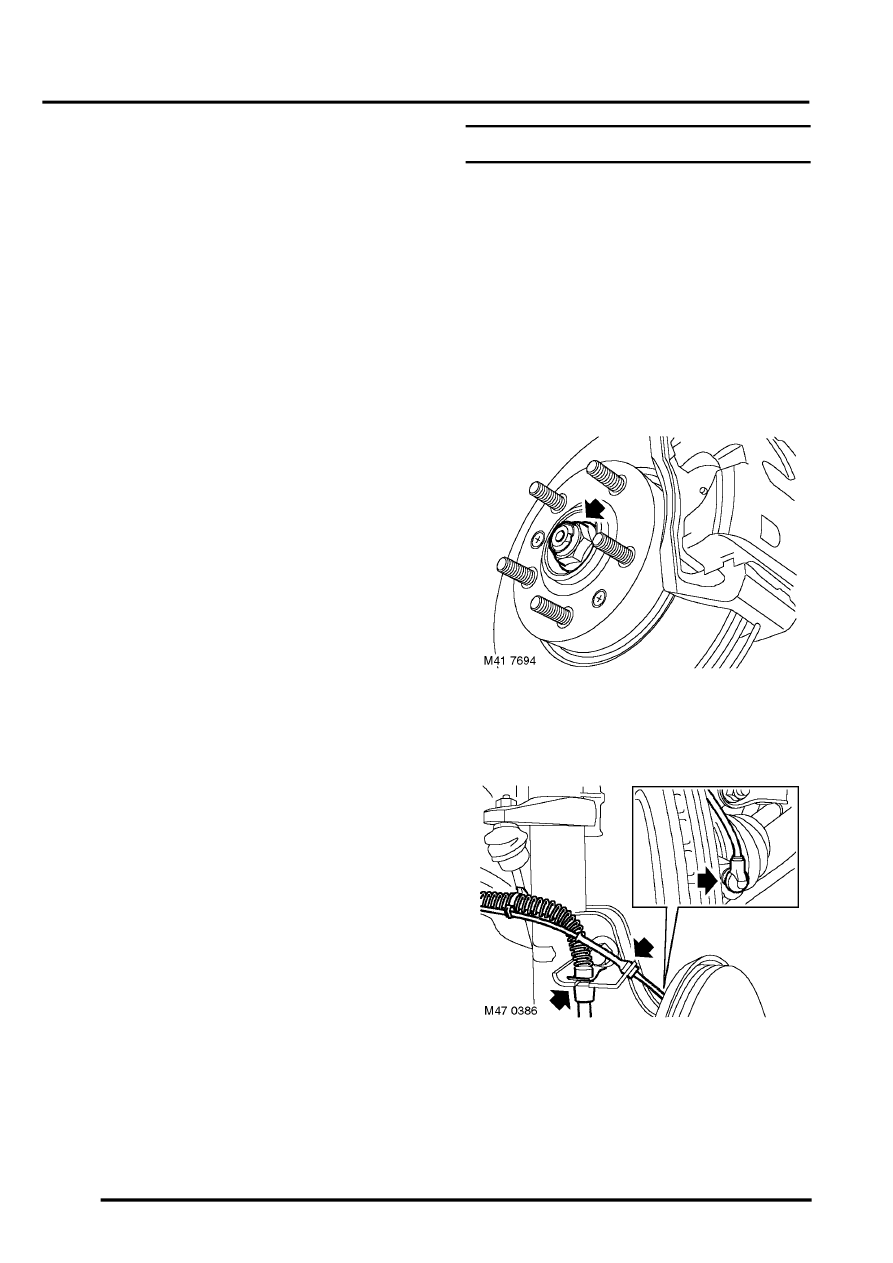
4. Release stake in drive shaft nuts.
5. With an assistant applying brakes, remove and
discard drive shaft hub nut.
6. Remove clip securing brake hose to bracket on
damper.
7. Release ABS sensor harness and brake hose
from damper.
8. Release ABS sensor from hub.
Parts & tools for this job Staging For Land Rover Freelander
- TOOLCoil spring compressorSearch: coil spring compressor
- TOOLBall joint separatorSearch: ball joint separator
- PARTFront shock absorbersSearch: Land Rover Freelander front shock absorbers
Links open Amazon search results in a new tab. As an Amazon Associate I earn from qualifying purchases.