
Bearing - hub (page 4 of 4)
- Make
- Land Rover
- Model
- Freelander Service Procedures
- Section
- REPAIRS
FRONT SUSPENSION
60-6
REPAIRS
Refit
1. Clean hub and drive flange.
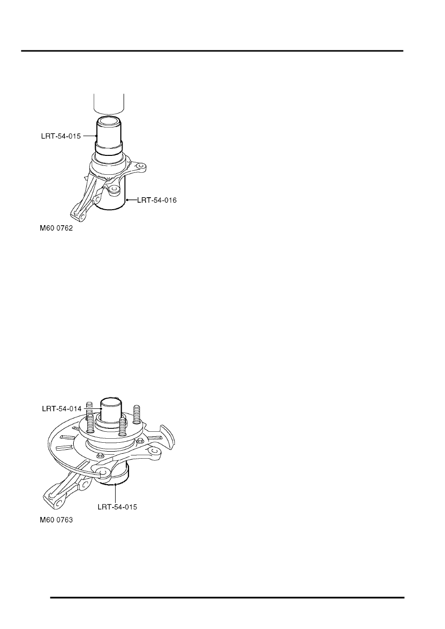
2. Support hub on tool LRT-54-016 and press in
new bearing using LRT-54-015.
CAUTION: One side of the bearing is
magnetic. The magnetic side is identifiable
by the application of a matt black finish. The
magnetic side must face towards the
inboard side of the vehicle. Before fitting
the bearing, ensure the magnetic face is
clean. The bearing must be handled with
extreme care.
3. Fit circlip to hub.
4. Fit brake disc shield, fit bolts and tighten to 8.5
Nm (6.5 lbf.ft).
5. Support bearing on tool LRT-54-015 and press
drive flange into bearing using LRT-54-014.
6. Clean drive shaft.
7. Fit hub assembly to lower joint, fit new nut and
tighten to 65 Nm (48 lbf.ft).
8. Fit drive shaft to hub.
9. Fit hub to damper, fit nuts and bolts and tighten
to 205 Nm (151 lbf.ft).
10. Clean brake disc to drive flange mating faces.
11. Fit disc to drive flange, align reference marks, fit
screws and tighten to 5 Nm (4 lbf.ft).
12. Clean mating faces of caliper and hub.
13. Position caliper to brake disc fit bolts and
tighten to 100 Nm (74 lbf.ft).
14. Fit brake hose to abutment bracket and fit clip.
15. Clean ABS sensor, smear sensor with an anti-
seize grease and fit sensor to hub.
CAUTION: Ensure ABS sensor is fully
located into hub, so that sensor touches
pole wheel teeth.
16. Fit ABS sensor lead to bracket.
17. Fit new drive shaft nut and tighten to 400 Nm
(295 lbf.ft). Stake nut to shaft.
18. Stake drive shaft hub nut.
19. Fit road wheel(s) and tighten nuts to 115 Nm
(85 lbf.ft).
20. Remove stands and lower vehicle.
Parts & tools for this job Staging For Land Rover Freelander
- PARTFront wheel bearingSearch: Land Rover Freelander front wheel bearing
- TOOLBearing puller kitSearch: wheel bearing puller kit
- PARTCV boot kitSearch: Land Rover Freelander cv boot kit
Links open Amazon search results in a new tab. As an Amazon Associate I earn from qualifying purchases.