
Cylinder head gasket - LH (page 3 of 3)
- Make
- Land Rover
- Model
- Freelander Service Procedures
- Section
- REPAIRS
ENGINE - K SERIES KV6
REPAIRS 12-3-15
Refit
1. Clean cylinder head mating face.
CAUTION: Use suitable gasket removal
spray and a plastic scraper.
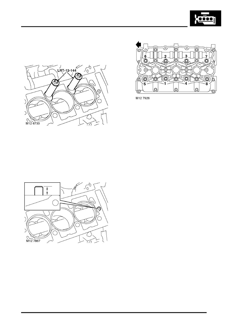
2. Remove bolts securing cylinder liner clamps
LRT-12-144 to cylinder block and remove
clamps.
CAUTION: Do not rotate crankshaft.
3. Clean cylinder block face and dowel holes.
4. Clean cylinder head bolts and wipe dry.
5. Lightly lubricate threads and beneath heads of
cylinder head bolts with clean engine oil.
6. Check that fitted height of dowels is between 10
to 11 mm (0.40 to 0.43 in) above cylinder block
top face. Replace dowels if fitted height is
incorrect.
7. Fit new cylinder head gasket onto cylinder
block with the word 'TOP' uppermost.
8. With assistance, fit cylinder head and carefully
position LH inlet to RH inlet manifold.
9. Carefully enter cylinder head bolts, DO NOT
DROP. Screw bolts into place by hand.
10. Tighten cylinder head bolts progressively in the
sequence shown to :
l
Stage 1 - 25 Nm (18 lbf.ft)
l
Stage 2 - Tighten in the same sequence to
25 Nm (18 lbf.ft)
l
Stage 3 -Tighten in the same sequence to
25 Nm (18 lbf.ft)
l
Stage 4 - Using an angle torque gauge,
tighten bolts in the same sequence a further
180
°
11. Fit LH camshaft cover gasket.
ENGINE - K SERIES KV6, REPAIRS,
Camshaft cover gasket - LH - Up to 03MY.
12. Remove and discard 'O' rings from injectors.
13. Clean injectors and injector locations in fuel rail.
14. Lubricate new 'O' rings with castor oil and fit to
injectors.
15. Position fuel rail assembly and secure injectors
to inlet manifolds.
16. Position injector protection cover - if fitted to RH
fuel rail and secure injector harness to
protection cover or fuel rail with clips.
17. Fit bolts securing fuel rail to inlet manifolds and
tighten to 9 Nm (7 lbf.ft).
18. Position CMP sensor bracket, fit and tighten
bolt to 9 Nm (7 lbf.ft).
19. Connect CMP sensor multiplug and secure to
bracket.
20. Connect breather hose to LH inlet manifold.
21. Connect coolant bleed hose to inlet manifold
and secure with clip.
22. Position ignition coils to LH inlet manifold.
23. Position earth lead, fit nuts and bolts securing
ignition coils to LH inlet manifold and tighten to
9 Nm (7 lbf.ft).
24. Position ht lead guide bracket, fit and tighten
special bolt.
25. Connect ht leads to spark plugs and secure ht
leads in guide clips.
26. Clean camshaft timing belt cover backplate
bolts and apply sealant, Part No. STC 50552 to
the first 3 threads.
Parts & tools for this job Staging For Land Rover Freelander
- PARTEngine gasket setSearch: Land Rover Freelander engine gasket set
- TOOLTorque wrenchSearch: 3/8 inch torque wrench
- TOOLFeeler gauge setSearch: feeler gauge set
Links open Amazon search results in a new tab. As an Amazon Associate I earn from qualifying purchases.