
Support bearing - front
- Make
- Land Rover
- Model
- Freelander Service Procedures
- Section
- REPAIRS › Support bearing - front
DRIVESHAFTS
47-16
REPAIRS
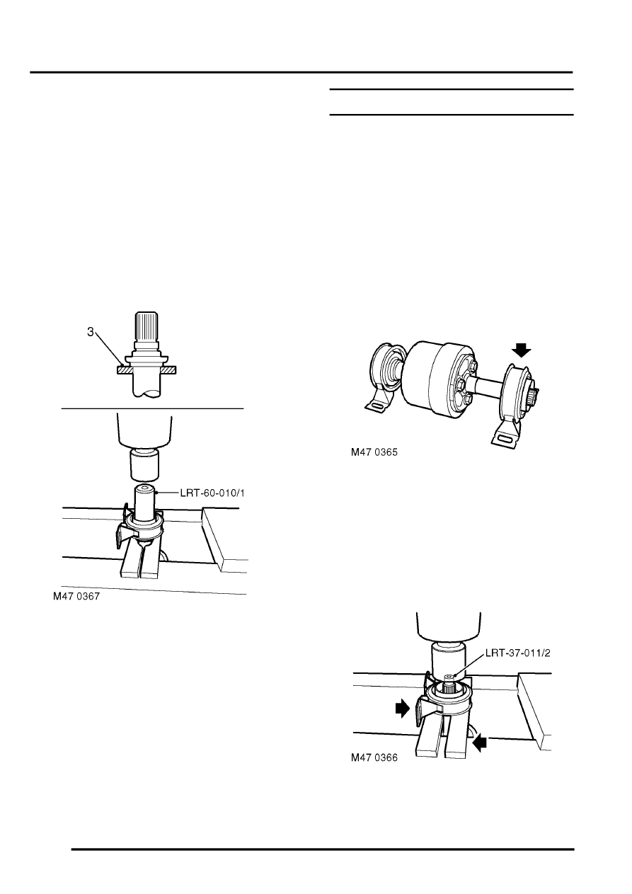
6. Position LRT-37-011/2 thrust button onto
viscous coupling splines.
7. With assistance, press the splined end of the
viscous coupling unit through the support
bearing. Take care that the viscous coupling
does not drop when free of the support bearing.
8. Remove viscous coupling assembly from
press.
Refit
1. Clean flinger, bearing journal, splines and
support bearings.
2. Ensure that cavities between bearing and outer
shrouds are packed with Texaco Novatex EP2
grease.
3. With assistance, position viscous coupling
assembly onto press bed and locate the press
bars onto collar on viscous coupling as shown.
4. Position LRT- 60-010/1 onto bearing inner
race, and with assistance, press support
bearing onto viscous coupling.
5. Remove viscous coupling assembly from
press.
6. Spin support bearing to confirm true running.
7. Fit front propeller shaft.
DRIVESHAFTS, REPAIRS, Propeller
8. Fit rear propeller shaft.
DRIVESHAFTS, REPAIRS, Propeller
Support bearing - front
$% 47.20.05
The procedure to replace the rear support bearing is
identical to that of the front.
Remove
1. Remove front propeller shaft.
DRIVESHAFTS, REPAIRS, Propeller
2. Remove rear propeller shaft.
DRIVESHAFTS, REPAIRS, Propeller
3. Note the fitted position of the support bearing
on the viscous coupling.
CAUTION: When removing and refitting any
components to viscous unit, full support
must be given using the flange adjacent to
the splines. Under no circumstances should
any load be applied through the viscous
unit bearings.
4. Position press bars to support bearing as
shown, taking care that the press bars are not
positioned on the steel flinger.
Parts & tools for this job Staging For Land Rover Freelander
- PARTFront wheel bearingSearch: Land Rover Freelander front wheel bearing
- TOOLBearing puller kitSearch: wheel bearing puller kit
- PARTCV boot kitSearch: Land Rover Freelander cv boot kit
Links open Amazon search results in a new tab. As an Amazon Associate I earn from qualifying purchases.