
Bell & joint - outer - rear
- Make
- Land Rover
- Model
- Freelander Service Procedures
- Section
- REPAIRS › Bell & joint - outer - rear
DRIVESHAFTS
47-8
REPAIRS
Gaiter - outer - rear
$% 47.11.03
Remove
1. Disconnect battery earth lead.
2. Raise rear of vehicle.
WARNING: Do not work on or under a
vehicle supported only by a jack. Always
support the vehicle on safety stands.
3. Remove road wheel.
4. Remove drive shaft outer joint.
5. Slide gaiter from shaft.
Refit
1. Clean drive shaft and gaiter.
2. Apply grease from the sachet to the joint.
3. Fit new gaiter to shaft.
4. Fit drive shaft outer joint.
5. Fit road wheel(s) and tighten nuts to 115 Nm
(85 lbf.ft).
6. Remove stands and lower vehicle.
7. Connect battery earth lead.
Bell & joint - outer - rear
$% 47.11.04
Remove
1. Disconnect battery earth lead.
2. Raise rear of vehicle.
WARNING: Do not work on or under a
vehicle supported only by a jack. Always
support the vehicle on safety stands.
3. Remove road wheel.
4. Remove drive shaft.
5. Place drive shaft in vice.
6. Release both gaiter clips and discard.
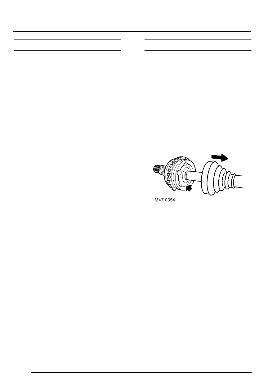
7. Slide gaiter along shaft to gain access to outer
joint.
8. Using a drift against the inner part of the joint,
remove joint from shaft.
9. Inspect gaiter for damage and renew if
necessary.
10. Remove and discard circlip from drive shaft.
Refit
1. Clean drive shaft and gaiter.
2. Fit new circlip to drive shaft.
3. Position outer joint to shaft, use a screwdriver
to press circlip into its groove and push joint
fully onto shaft.
4. Apply grease from the sachet to the joint.
5. Position gaiter to joint and use a 'Band-it
thriftool' LRT-99-019 to secure the 2 new clips.
6. Fit drive shaft.
7. Fit road wheel(s) and tighten nuts to 115 Nm
(85 lbf.ft).
8. Remove stands and lower vehicle.
9. Connect battery earth lead.
Parts & tools for this job Staging For Land Rover Freelander
- PARTRear wheel bearingSearch: Land Rover Freelander rear wheel bearing
- TOOLBearing puller kitSearch: wheel bearing puller kit
- PARTCV boot kitSearch: Land Rover Freelander cv boot kit
Links open Amazon search results in a new tab. As an Amazon Associate I earn from qualifying purchases.