
High Pressure Hose
- Make
- Land Rover
- Model
- Freelander System Description and Operation
- Section
- Description › High Pressure Hose
STEERING
DESCRIPTION AND OPERATION
57-9
An oval cam ring is located in the body. Ten roller vanes are housed in a carrier and rotate within the cam ring. The
carrier is mounted in the centre of the shaft and receives positive drive from the shaft via a drive pin. The carrier is
seated against an end plate which is located in the cover. The front of the carrier is covered by a port plate which is
located against a seal plate in the body. The port plate controls the fluid flow into and out of the roller vanes during
their cycle.
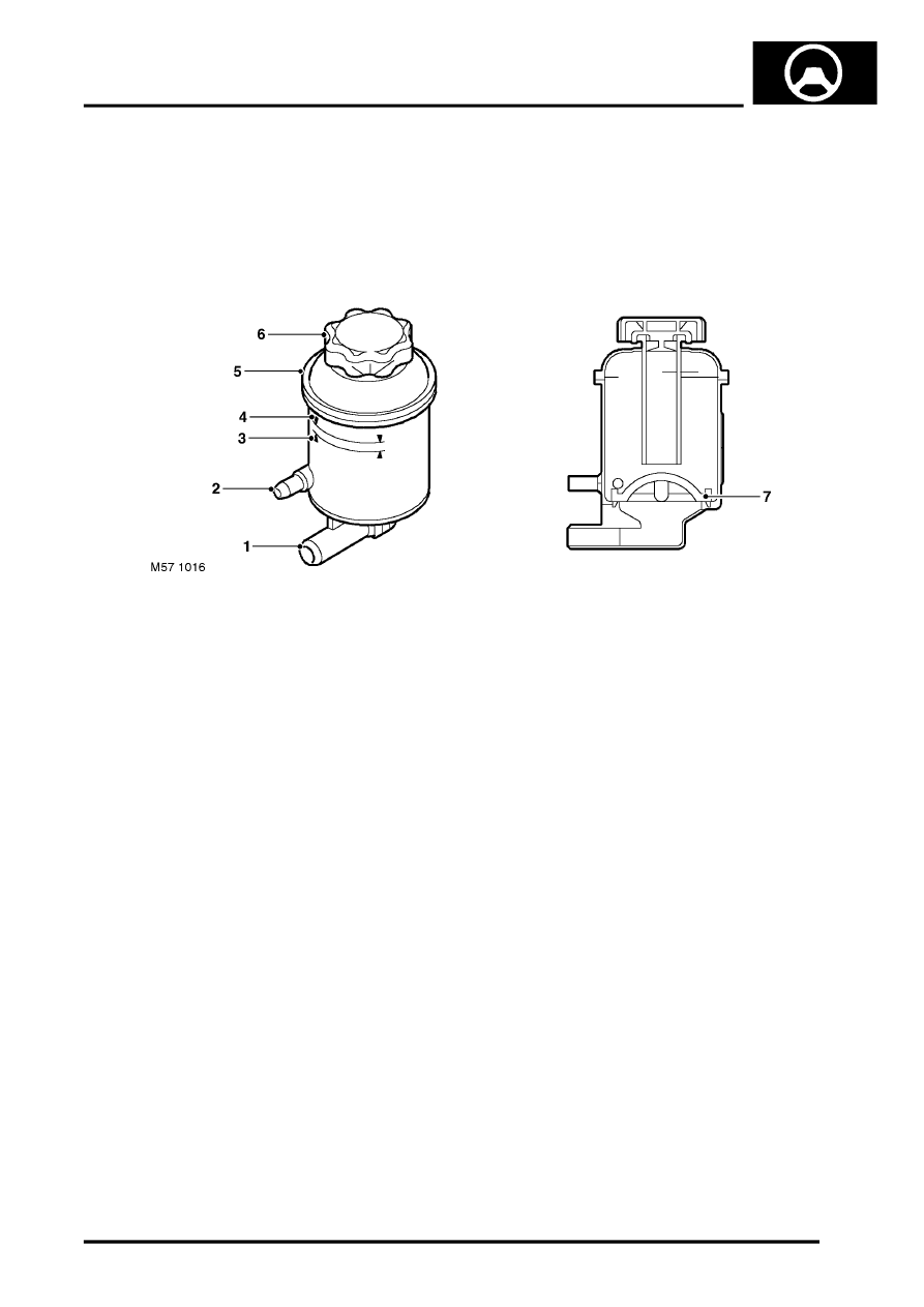
Fluid Reservoir
1 Supply connection
2 Return connection
3 Lower fluid level mark
4 Upper fluid level mark
5 Reservoir body
6 Cap
7 Filter assembly
The fluid reservoir is mounted in the right hand side of the engine compartment on a bracket attached to the inner
wing.
The reservoir comprises a body, a cap and a filter assembly. The reservoir has a capacity to the upper level mark of
335 cc.
An 'O' ring seal in the cap prevents leakage. The cap is pushed onto the latch and turned through 90
°
to lock. A
breather hole is incorporated in the cap to allow changes in fluid level during operation.
A filter assembly is fitted into the bottom of the reservoir. The filter is made from fine nylon mesh which is moulded
into the frame of the filter. The filter removes particulate matter from the fluid before it is drawn into the supply
connection and is non-serviceable.
The primary function of the fluid reservoir is to hold a surplus of hydraulic fluid in the system to allow for expansion
and contraction of the fluid due to temperature variations. The fluid level ensures that the supply connection is covered
with fluid at all operational attitudes. Any air that may be present in the hydraulic system will be exhausted from the
fluid at the reservoir.
High Pressure Hose
The high pressure hose connecting the PAS pump to the valve unit incorporates an attenuator. The attenuator
comprises a bullet shaped valve which is located between two spiral wound springs. The valve operates as a restrictor
to damp pressure pulses from the PAS pump, reducing noise and strain on downstream components. The attenuator
is integral with the hose and cannot be serviced separately.
Parts & tools for this job Staging For Land Rover Freelander
- TOOLTie rod end toolSearch: tie rod end puller
- TOOLBall joint separatorSearch: ball joint separator
- FLUIDPower steering fluidSearch: Land Rover power steering fluid
Links open Amazon search results in a new tab. As an Amazon Associate I earn from qualifying purchases.