
Fuel Level Gauge (page 2 of 2)
- Make
- Land Rover
- Model
- Freelander System Description and Operation
- Section
- Description
INSTRUMENTS
88-10
DESCRIPTION AND OPERATION
Fuel Level Gauge – From 2002.5 Model Year
A new design fuel level sensor is introduced from 2002.5 model year. Unlike the previous sensor, this sensor is sealed
from the fuel preventing contamination of the contacts.
The new sensor requires modifications to the instrument pack fuel gauge calibration, therefore, the new sensor cannot
be fitted to a pre 2005.5 model year vehicle.
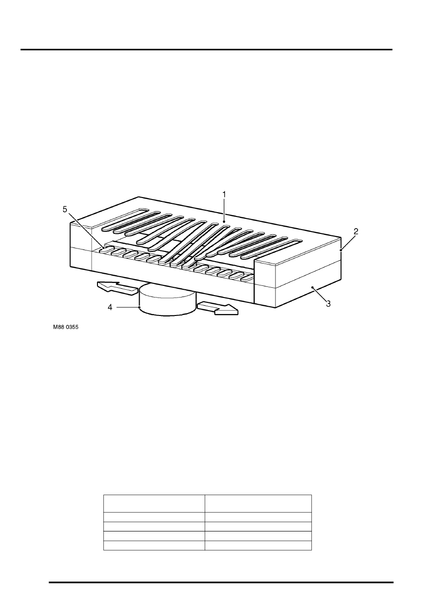
The sensor is a MAgnetic Passive Position Sensor (MAPPS) which provides a variable resistance to earth for the
output from the fuel gauge. The gauge comprises a series of 51 film resistors mounted in an arc on a ceramic surface.
The resistors are wired in series with individual contacts. A soft magnetic foil with 51 flexible contacts is mounted a
small distance above the film resistors. A magnet, located below the ceramic surface, is attached to the sender unit
float arm. As the float arm moves the magnet follows the same arc as the film resistors. The magnet pulls the flexible
contacts onto the opposite film resistor contacts forming an electrical circuit.
Sensor Operating Principle
1 Magnetic foil
2 Spacer
3 Ceramic surface
4 Magnet
5 Resistance film
The film resistors are arranged in a linear arc with resistance ranging from 50 to 1000
Ω
. The electrical output signal
is output proportional to the amount of fuel in the tank and the position of the float arm. The measured resistance is
processed by the instrument pack to implement an anti-slosh function. This monitors the signal and updates the fuel
gauge pointer position at regular intervals, preventing constant pointer movement caused by fuel movement in the
tank due to cornering or braking.
A warning lamp is incorporated into the face of the fuel gauge and illuminates when the fuel level is at or below 1.5
gallons (7 litres).
The fuel level sender signal is converted into a CAN message by the instrument pack as a direct interpretation of the
fuel tank contents in litres. The ECM uses the CAN message to suspend OBD misfire detection when the fuel level is
below 15% capacity.
Fuel Gauge Resistance/Read out Table – From 2002.5 Model Year
Petrol Engines – Sender Unit
Resistance, Ohms
Nominal Gauge Reading
101 - 106
Empty
176
Low fuel level illumination
340
Half full
549 - 554
Full
Parts & tools for this job Staging For Land Rover Freelander
- TOOLTorque wrenchSearch: 3/8 inch torque wrench
- TOOLSocket setSearch: socket set metric
- BOOKHaynes manualSearch: Haynes manual Land Rover Freelander
Links open Amazon search results in a new tab. As an Amazon Associate I earn from qualifying purchases.