
Ignition Coils – From 2003 Model Year
- Make
- Land Rover
- Model
- Freelander System Description and Operation
- Section
- Description › Ignition Coils – From 2003 Model Year
ENGINE MANAGEMENT SYSTEM - SIEMENS
18-4-28 DESCRIPTION AND OPERATION
Ignition Coils – From 2003 Model Year
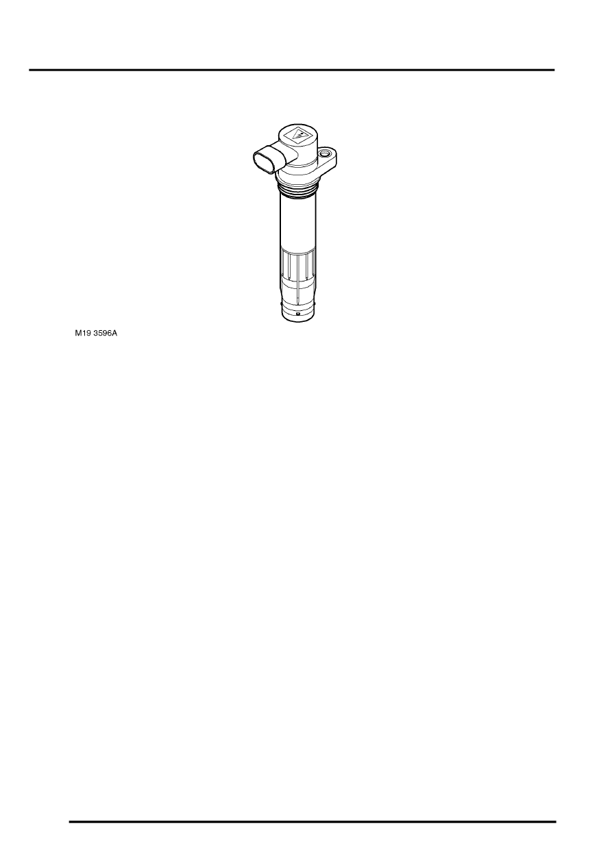
A new 'pencil' type ignition coil is introduced at 2003 model year. This coil is used on all six cylinders and replaces the
two coils used previously. The ECM uses a separate ignition coil for each spark plug. The ignition coils are of the plug
top 'pencil' design which attach to the top of the spark plug. The coils are secured to the camshaft cover with a screw.
The coil has a ribbed area which seals the coil in the spark plug hole in the cylinder head, preventing the ingress of
moisture and debris around the spark plug. These coils eliminate the requirement for HT leads which in turn improves
the ignition system reliability.
Each coil has a three pin female connector which provide for a battery voltage ignition feed from the main relay, an
earth for the secondary winding and a primary winding negative (switch) terminal. The switch terminal of each coil is
connected to a separate pin on the ECM to allow independent switching.
The ignition coils are charged when the ECM provides an earth path to the primary winding negative terminal. The
duration of the charge time is maintained relatively constant by the ECM for all engine speeds with the dwell period
increasing with engine speed. This type of system, referred to as constant energy, allows the use of low impedance
coils with faster charge times and higher outputs. The dwell period is calculated by the ECM using a closed loop
system to limit the current in the system and minimise output energy at low engine speeds. The ECM calculates the
dwell angle using the following inputs for reference:
l
Battery voltage (from main relay)
l
CKP sensor
l
Ignition coil primary current (from internal connection within the ECM).
The primary coil has a resistance of approximately 0.547
Ω
. The secondary coil resistance cannot be measured due
to a diode in the secondary winding. The ECM monitors the ignition system using the misfire detection function.
The spark is produced when the ECM breaks the primary coil winding circuit. This causes the magnetic flux around
the primary winding to collapse, inducing HT energy in the secondary coil, which can only pass to earth by bridging
the air gap of the spark plug.
Parts & tools for this job Staging For Land Rover Freelander
- PARTSpark plugsSearch: Land Rover Freelander spark plugs
- TOOLSpark plug socketSearch: spark plug socket
- TOOLSpark plug gap toolSearch: spark plug gap tool
Links open Amazon search results in a new tab. As an Amazon Associate I earn from qualifying purchases.