
Sensors
- Make
- Land Rover
- Model
- Freelander System Description and Operation
- Section
- Description › Sensors
DRIVING AIDS
DESCRIPTION AND OPERATION
86-2-5
Sensors
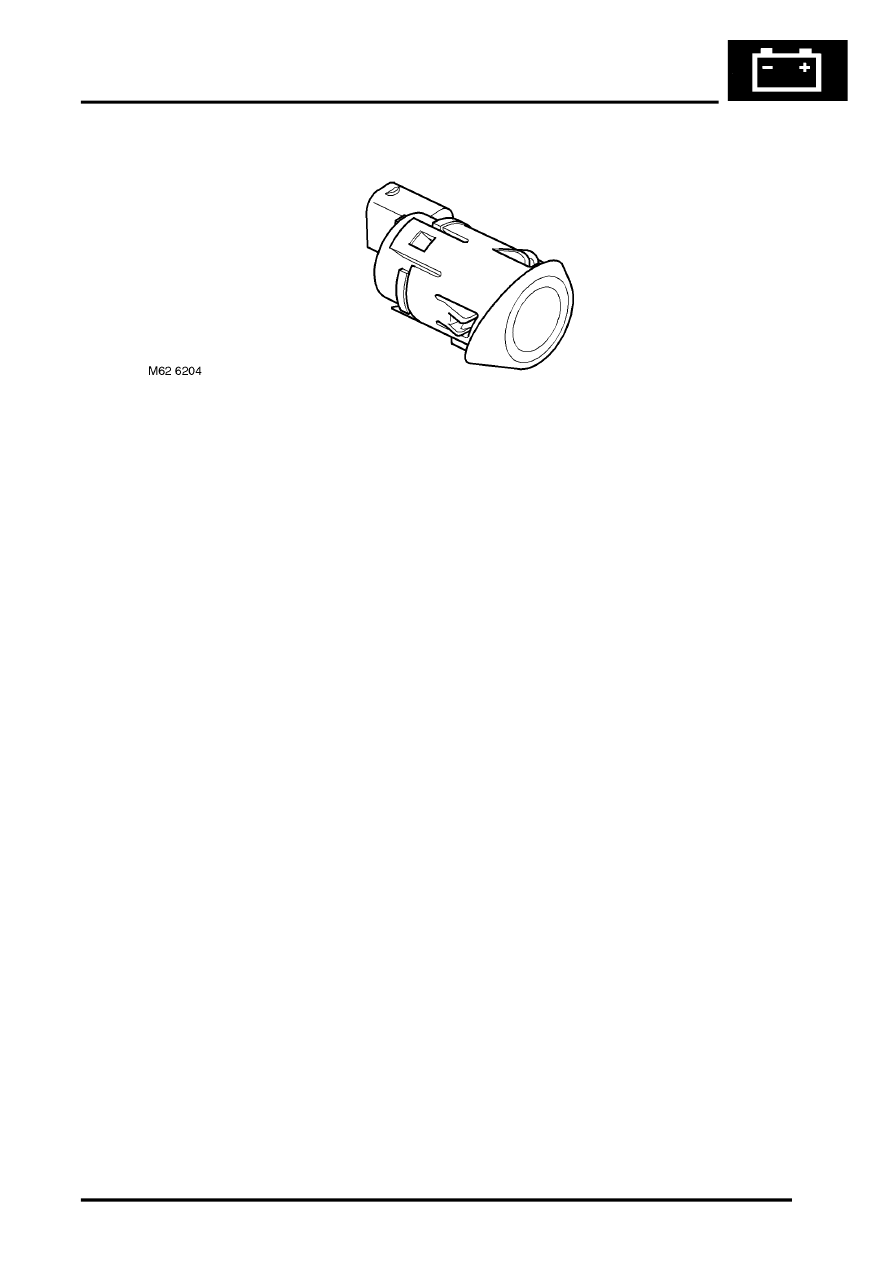
Four sensors are positioned in the rear bumper. Each sensor comprises an outer housing with an angled rubber trim
which differs between the inner and outer sensors and the sensor body. The outer housing has a slot which engages
with a pin on the sensor body and is locked by rotating the sensor. A coil spring around the sensor is compressed
when the sensor is installed in the bumper and maintains the sensor housing engaged on the pin. The sensor housing
has a raised lip at the top which locates in a corresponding groove in the bumper mounting hole and sets the correct
orientation for the sensor body.
Each sensor has a three pin connector which connects into a common harness linking all four sensors. This harness
is connected to the main vehicle body harness. The three pins are for sensor negative and positive feeds and a signal
line.
Each sensor comprises a plastic housing which contains a piezoelectric disc. The disc resonates at a frequency of
38.4kHz, producing an ultrasonic signal output. The disc also receives the reflected echo signal.
The PDC ECU controls the operating mode of each sensor by output of a digital signal on the signal line. Each sensor
has two modes of operation; combined transmitter and receiver mode or receiver mode only.
In the combined mode, the sensor emits a series of ultrasonic impulses and then switches to receiver mode to receive
the echo reflected by an obstacle in the detection range. These echo signals are amplified and converted from an
analogue signal to a digital signal by the sensor. The digital signal is then transmitted to the PDC ECU and compared
with preprogrammed data stored in an EEPROM within the ECU. The ECU receives this data via the signal line from
the sensor and calculates the distance to the obstacle according to the elapsed time between the transmitted and
received impulse. The duration of the impulse transmission is determined by the module. The sensor determines the
frequency of the impulse.
In the receiver mode, the sensor will receive impulses that were emitted by adjacent sensors. The ECU uses this
information to precisely determine position and distance of the obstacle.
Parts & tools for this job Staging For Land Rover Freelander
- TOOLOBD2 scannerSearch: OBD2 scanner
- TOOLDigital multimeterSearch: automotive digital multimeter
- TOOLBack-probe test leadsSearch: back probe test leads
Links open Amazon search results in a new tab. As an Amazon Associate I earn from qualifying purchases.