
Controller Area Network (CAN) Bus
- Make
- Land Rover
- Model
- Freelander System Description and Operation
- Section
- Description › Controller Area Network (CAN) Bus
AUTOMATIC GEARBOX - JATCO
DESCRIPTION AND OPERATION
44-41
Controller Area Network (CAN) Bus
The CAN bus is a high speed broadcast network between the ECM, instrument pack, ABS ECU and the EAT ECU
allowing fast exchange of data between the ECU's every few microseconds.
The bus comprises two wires which are identified as CAN low (L) and CAN high (H). The wires are twisted together
to minimise the electromagnetic interference (noise) produced by the CAN messages.
To prevent message errors from electrical reflections, 120
Ω
resistors are incorporated into the CAN wire terminals of
the ECM, instrument pack, ABS ECU and the EAT ECU.
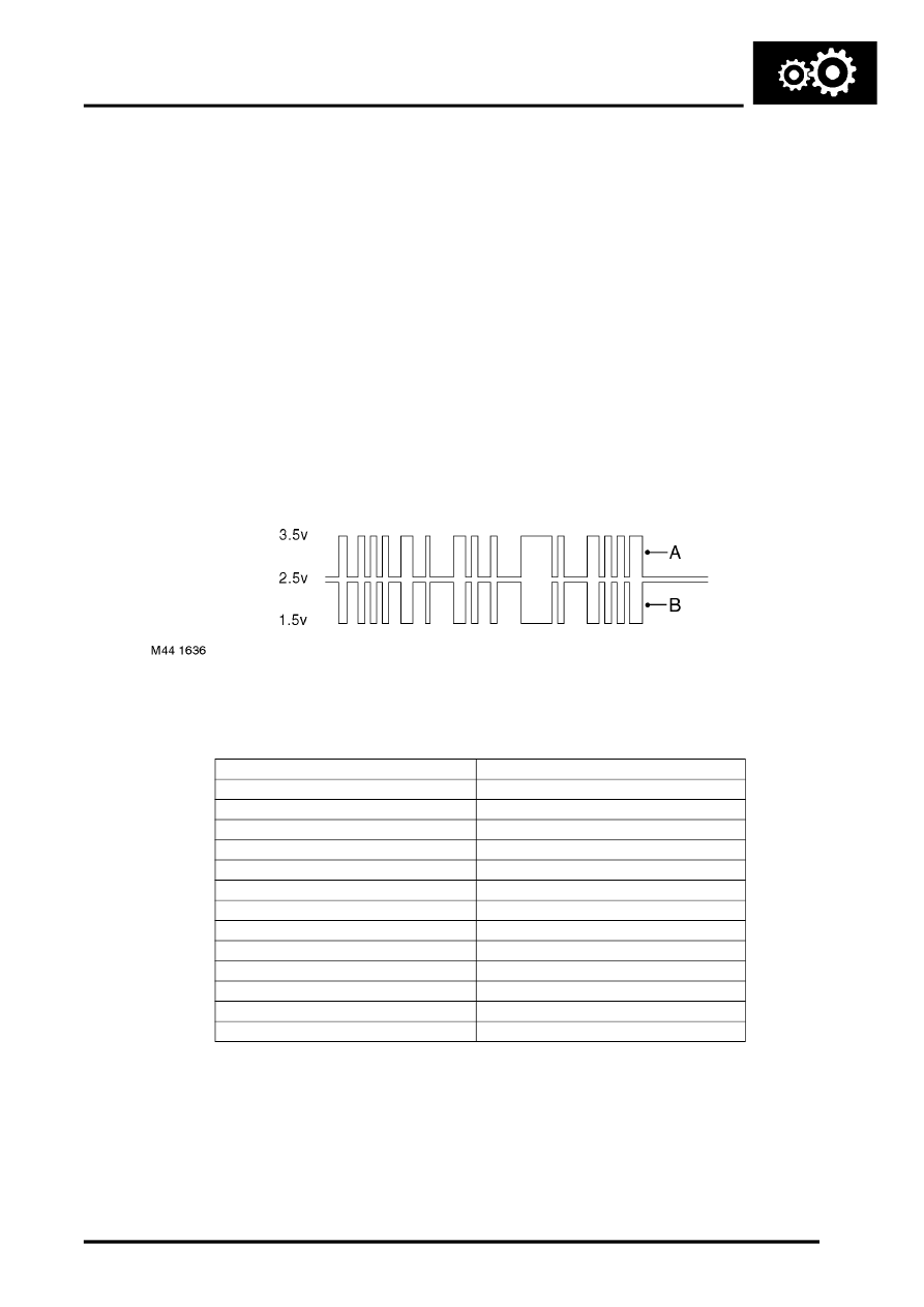
CAN messages consist of a signal which is simultaneously transmitted, in opposite phase, on both wires. CAN L
switches between 2.5 and 1.5 volts, while CAN H switches between 2.5 and 3.5 volts. This causes a potential
difference between the two lines to switch between 0 volt (logic 1) and 2 volts (logic 0) to produce the digital signal
message.
In the event of a CAN bus failure any of the following symptoms may be observed:
l
Transmission defaults to 4th gear
l
Torque converter lock-up control is disabled
l
Transmission of torque reduction message to the ECM is inhibited.
CAN Bus Switching
EAT ECU CAN Messages
The following table lists CAN message inputs and outputs from and to the EAT ECU.
Inputs
Outputs
Actual engine torque
Cooling request
Engine coolant temperature
Current/Target gear
Engine friction
Gear selector lever position
Engine speed
Gear shift in progress
Engine speed signal error
Gearbox fault status
Engine torque error
Torque reduction request
Ignition switch status
Gearbox MIL Status
Actual engine torque
Gear shift mode
Estimated engine torque
Throttle angle (driver demand)
Torque reduction status
Engine MIL status
Hill descent activity status
Parts & tools for this job Staging For Land Rover Freelander
- PARTTransmission filter kitSearch: Land Rover Freelander transmission filter kit
- FLUIDAutomatic transmission fluidSearch: Land Rover automatic transmission fluid
- TOOLFluid transfer pumpSearch: fluid transfer pump
Links open Amazon search results in a new tab. As an Amazon Associate I earn from qualifying purchases.