
Power unit with automatic transmission r + r
- Make
- Fiat
- Model
- Ulysse Factory Service Manual
- Year
- 2002–2010
- Section
- Engine and power unit › Power unit with automatic transmission r + r
POWER UNIT WITH AUTOMATIC TRANSMISSION R + R
Removing
Position the vehicle on a lift.
Disconnect the negative battery terminal.
| Description | Connector | |
|---|---|---|
| Battery | A001B |
Op. 7055B54 UNDER-ENGINE GUARD - R R
Op. 4450B12 FRONT OR REAR WHEELS (TWO) - R+R
Op. 7055B90 LEFT FRONT WHEEL ARCH LINER - R.R.
Op. 7055B91 RIGHT FRONT WHEEL ARCH LINER - R.R.
Position a suitable container for collecting the engine coolant.
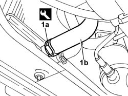
1. Loosen the retaining band (1a) using the special tool, disconnect the lower hose (1b) from the radiator and completely drain the engine coolant into the container.
| Description | Code | Function | |
|---|---|---|---|
| 1a | Caliper | 1.881.138.000 | Band opening |
Op. 0010T84 COOLANT FOR AIR CONDITIONING SYSTEM DEHYDRATE AND RECHARGE
Op. 5540B78 LEFT FRONT LIGHT CLUSTER WITH TURN SIGNAL AND FOGLAMP R R
Op. 5540B79 RIGHT FRONT LIGHT CLUSTER WITH TURN SIGNAL AND FOGLAMP R R
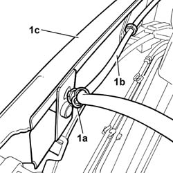
1. Open the retaining bands (1a) and release the headlamp washer fluid supply pipe (1b) from the upper front crossmember (1c).
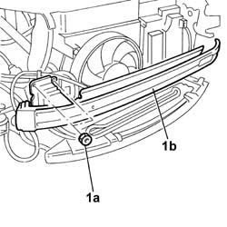
1. Undo the fixing nuts (1a), on both sides, and remove the upper crossmember (1b).
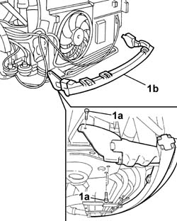
1. Undo the fixing bolts (1a), on both sides, and remove the lower crossmember (1b).
1. Disconnect the bonnet release control cable from the lock.
2. Undo the fixing bolts (2a) and remove the bonnet lock (2b) from the housing.
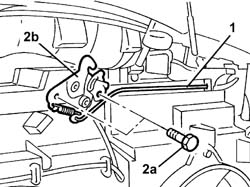
1. Disconnect the electrical connection for the bonnet opening switch incorporated in the actual lock.
| Description | Connector | |
|---|---|---|
| 1 | Bonnet release switch | See I010 Bonnet release switch |
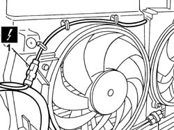
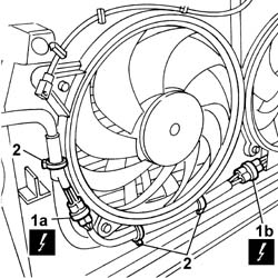
1. Disconnect the electrical connectors for the radiator fans.
2. Release the wiring from the bands and move it aside to free up the work area.
| Description | Connector | |
|---|---|---|
| 1a | Engine fan motor | See N011 |
| Description | Connector | |
|---|---|---|
| 1b | Engine fan motor - 2 | See N012 |
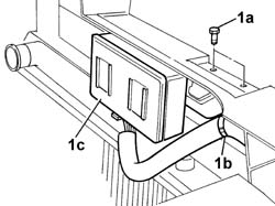
1. Undo the fixing bolts (1a), remove the fastening bands (1b), remove the relay control unit (1c) and place it at the side to free up the work area.
1. Loosen the band (1a) and disconnect the pipe (1b) from the coolant manifold to the radiator.
| Description | Code | Function | |
|---|---|---|---|
| 1a | Caliper | 1.881.138.000 | Band opening |
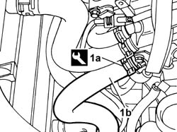
1. Loosen the bands (1a) using the special tool, then disconnect and remove the upper coolant inlet pipe from the manifold to the radiator (1b).
| Description | Code | Function | |
|---|---|---|---|
| 1a | Caliper | 1.881.138.000 | Band opening |
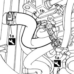
1. Loosen the band (1a) using the special tool, then disconnect and remove the coolant supply pipe (1b) to the automatic transmission fluid heat exchanger from the radiator.
| Description | Code | Function | |
|---|---|---|---|
| 1a | Caliper | 1.881.138.000 | Band opening |
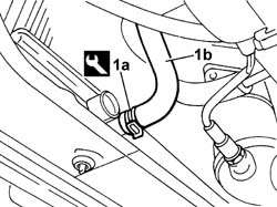
1. Loosen the band (1a) using the special tool, then disconnect and remove the coolant supply pipe (1b) from the automatic transmission fluid heat exchanger.
| Description | Code | Function | |
|---|---|---|---|
| 1a | Caliper | 1.881.138.000 | Band opening |
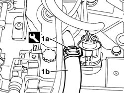
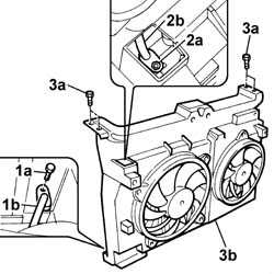
1. Undo the fixing bolt (1a) and disconnect the lower pipe (1b) for the air conditioning system condenser.
2. Undo the fixing bolt (2a) and disconnect the upper pipe (1b) for the air conditioning system condenser.
3. Undo the fixing bolts (3a) and remove the radiator - fans - condenser assembly (3b).
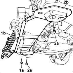
1. Undo the fixing bolts (1a) and move the power assisted steering system pipes (1b) aside complete with mounting brackets.
2. Undo the fixing bolts (2a) and remove the lower crossmember (2b).
Op. 1048A47 SLEEVE FROM RIGID PIPE TO THROTTLE BODY - R R
Op. 1048A10 AIR CLEANER FILTERING ELEMENT - REPLACE
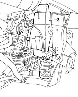
1. Undo the nuts and the bolts fixing the air filter casing mounting bracket.
2. Release the air filter casing flexible cold air intake pipe from the support.
3. Remove the air filter casing mounting bracket complete with mechanical vehicle lifting device.
Op. 4130B10 POWER STEERING FLUID RESEVOIR R R
Op. 4130B12 POWER STEERING FLUID RESERVOIR MOUNTING/BRACKETS - POSITION
Op. 5010B18 CLIMATE CONTROL UNIT AIR INTAKE - R.R.
Op. 5050B34 WINDSCREEN WIPER ARM/S COMPLETE WITH BLADE - R+R
Op. 7210E22 WINDSCREEN BASE TRIM
Op. 1088B10 ENGINE COOLING TANK - R + R
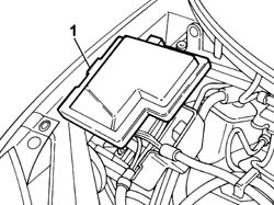
1. Remove the junction unit cover.
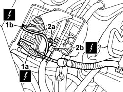
1. Disconnect the electrical connections (1a) for the engine wiring and the two-way connector (1b), then release the wiring and move it aside.
2. Undo the fixing nut (2a), disconnect the end of the cable (2b) and move the wiring aside.
| Description | Connector | |
|---|---|---|
| 1a | Engine compartment junction unit | B001B |
| Description | Connector | |
|---|---|---|
| 1b | Engine compartment junction unit | B001D |
| Description | Connector | |
|---|---|---|
| 2b | Engine compartment junction unit | B001A |
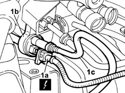
1. Disconnect the electrical connection (1a), release the fuel vapour cut out valve (1b) from the mounting bracket and disconnect the vapour recovery pipe (1c).
| Description | Connector | |
|---|---|---|
| 1a | Fuel vapour recovery solenoid valve | See L010 Fuel vapour recovery solenoid valve |
Op. 1040B32 FUEL FILLER PIPE UNION SLEEVE - R + R
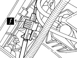
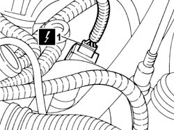
1. Working on the right head, timing side, disconnect the electrical connection for the upper Lambda sensor on the left pre-catalyzer.
| Description | Connector | |
|---|---|---|
| 1 | Lambda sensor on pre-catalyzer | See K015 Lambda sensor on pre-catalyzer |
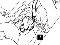
1. Working on the right head, flywheel side, disconnect the electrical connection for the lower Lambda sensor on the left pre-catalyzer.
| Description | Connector | |
|---|---|---|
| 1 | Lambda sensor on catalyzer | See K017 Lambda sensor on catalyzer |
1. Working on the right head, flywheel side, disconnect the electrical connection for the lower Lambda sensor on the left pre-catalyzer.
| Description | Connector | |
|---|---|---|
| 1 | Lambda sensor on catalyzer - 2 | See K018 Lambda sensor on catalyzer - 2 |
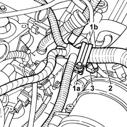
1. Undo the fixing bolt (1a) and remove the mounting collar (1b).
2. Move the wiring to free up the work area.
3. Disconnect the electrical connection from the engine coolant temperature sensor.
| Description | Connector | |
|---|---|---|
| 3 | Engine coolant temperature sensor/sender unit | See K036 Engine coolant temperature sensor/sender unit |
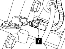
1. Disconnect the electrical connection from the engine rpm sensor located on the bellhousing by the flywheel.
| Description | Connector | |
|---|---|---|
| 1 | Rpm sensor | See K046 Rpm sensor |
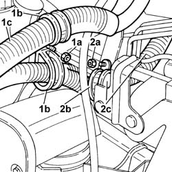
1. Undo the fixing nut (1a), remove the securing bands (1b) and release the wiring (1c).
2. Undo the fixing nut (2a), remove the securing band (2b) and release the wiring (1c).
1. Undo the retaining bolts (1a) and remove the engine management control unit guard (1b).
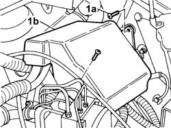
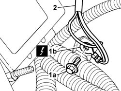
1. Undo the fixing bolt (1a) and detach the wiring earth connection (1b).
| Description | Connector | |
|---|---|---|
| 1b | Left front earth | C010A |
2. Release the wiring from the mountings and move it aside to free up the work area.
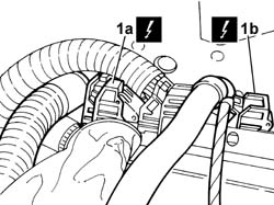
1. Disconnect the electrical connections (1a) and (1b) from the injection/ignition system control unit.
| Description | Connector | |
|---|---|---|
| 1a | Engine management control unit | M010B |
| Description | Connector | |
|---|---|---|
| 1b | Engine management control unit | M010C |
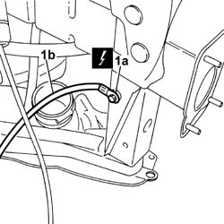
1. Undo the fixing bolt (1a) and release the automatic transmission earth lead (1b) from the body.
| Description | Connector | |
|---|---|---|
| 1b | Left front earth | C010B |
1. Release the end of the bowden cable from the gear selector lever.
Before releasing the end of the bowden cable, lock the gear selector lever.
2. Undo the fixing bolts (2a) and move the mounting bracket (2b) complete with bowden gear selector cable.
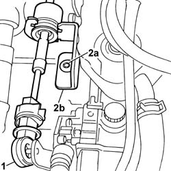
Move the engine cable looms to free up the work area.
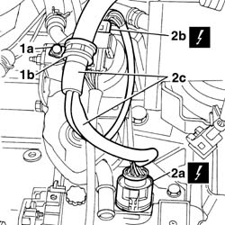
1. Undo the fixing bolt (1b) and remove the band (1b).
2. Disconnect the connector (2) located on the solenoid valve unit and the connector (2b) for the gear selector wiring and move the cable loom (2c) aside.
| Description | Connector | |
|---|---|---|
| 2a | Automatic transmission solenoid valves | See L050 Automatic transmission solenoid valves |
2b - Gear controls H037
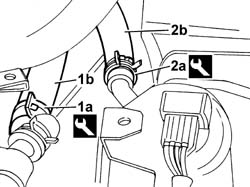
1. Loosen the retaining band (1a) using the special tool and disconnect the passenger compartment heater supply pipe (1b).
2. Loosen the retaining band (2a) using the special tool and disconnect the engine automatic transmission fluid heat exchanger return pipe (2b).
| Description | Code | Function | |
|---|---|---|---|
| 1a | Caliper | 1.881.138.000 | Band opening |
| Description | Code | Function | |
|---|---|---|---|
| 2a | Caliper | 1.881.138.000 | Band opening |
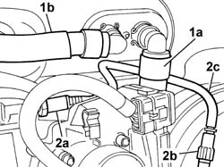
1. Disconnect the rapid connectors (1a) for the supply pipe (1b) and for the passenger compartment heater coolant return pipe.
2. Disconnect the rapid connectors (2a) on the intake chamber and (2b) on the brake servo and remove the vacuum intake pipe (2c).
1. Undo retaining bolt (1a) and remove the end (1b) supply and return pipes from the air conditioning compressor.
Seal the end of the pipes and the seats in the compressor.
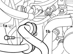
1. Disconnect the electrical connection for the power assisted steering fluid pressure sensor.
| Description | Connector | |
|---|---|---|
| 1 | Steering pressure sensor | Vedere K058 SENSORE PRESSIONE STERZO |
2. Undo the connector (2a) and disconnect the power assisted steering box supply pipe. Undo the fixing bolts (2b) and move the supply pipe (2c) aside to free up the work area.
3. Loosen the retaining band (3a) using the special tool and disconnect the return pipe (3b) from the power assisted steering pump.
| Description | Code | Function | |
|---|---|---|---|
| 3a | Caliper | 1.881.138.000 | Band opening |
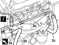
1. Release the power assisted steering box supply pipe (1b) from the retaining clips (1a).
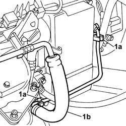
1. Undo the retaining bolts (1a) and remove the heat shield (1b) from the left exhaust manifold.
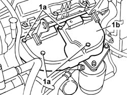
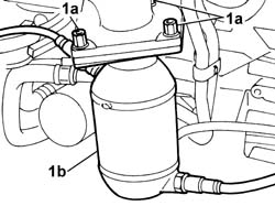
1. Undo the fixing nuts (1a) and detach the left pre-catalyaer (1b) from the exhaust manifold.
Position a suitable support to prevent the flexible section of the exhaust pipe from being distorted.
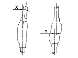
1. Do not distort the front flexible pipe beyond the angular value of X = 20° and the cutting value of Y = 25 mm.
The front flexible pipe should be protected against all mechanical attack from the outside. It should not come into contact with corrosive products; the front flexible pipe cannot withstand any distortion when it is in position.
Failure to follow these precautions will result in the shortening of the life of the flexible pipe; separation or dismantling the exhaust line is compulsory for operations that require the power unit to be raised.
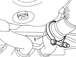
1. Loosen the band joined to the right pre-catalyzer pipe and release it from its housing.
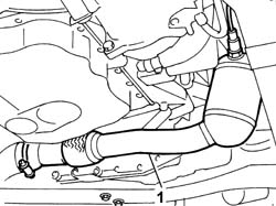
1. Working carefully in order not to damage the Lambda sensors and the flexible pipe, remove the pre-catalyzer from the vehicle.
Op. 1080B39 RIGHT CATALYTIC PRECONVERTER R R OR REPLACE CYLINDER HEAD GASKET
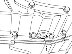
Position a suitable container for collecting the transmission fluid.
1. Undo the plug and drain the transmission fluid.
Op. 7055B65 ENGINGE BAY DUSTGUARD PROTECTION IN LEFT FRONT WHEEL ARCH R R
Op. 1048A23 COLD AIR INTAKE - R R
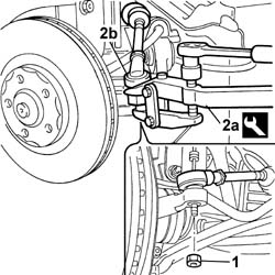
Working on both sides of the vehicle:
1. Undo the nut fixing the track rod end to the steering knuckle.
2. Extract the track rod end (2b) from the housing in the steering knuckle using the tool (2a).
| Description | Code | Function | |
|---|---|---|---|
| 2a | Head extractor | 1.847.035.000 | Ball joint removal |
Working on the left side of the vehicle:
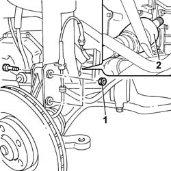
Release the ABS cables for the brake pad wear sensor and the brake control pipe from the mounting brackets.
1. Undo the bolts fixing the steering knuckle to the shock absorber.
2. Release the inner constant velocity joint for the driveshaft from the housing in the differential.
Working on the right side of the vehicle:
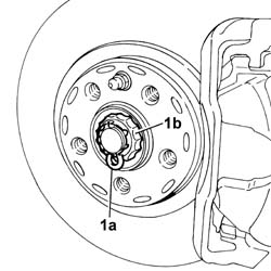
Release the ABS cables for the brake pad wear sensor and the brake control pipe from the mounting brackets.
1. Remove the split pin (1a) and remove the safety chamber (1b), then undo the nut underneath.
1. Undo the bolts fixing the steering knuckle to the shock absorber.
2. Fold the steering knuckle downwards and release the right driveshaft from the housing.
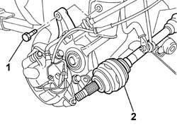
1. Undo the fixing nuts (1a) and remove the heat shield (1b).
2. Undo the bolts securing the right driveshaft assembly to the support.
3. Release the right driveshaft assembly from the vehicle.
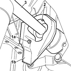
1. Undo the retaining bolts (1a) and remove the lower centre reaction rod (1b).
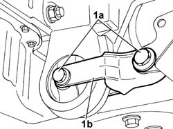
1. Undo the retaining bolts (1a) and remove the lower centre reaction rod support (1b).
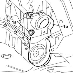
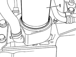
1. Undo and remove the engine oil filter element.
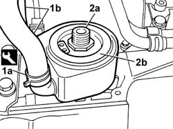
1. Loosen the band (1a) using the special tool and disconnect the heat exchanger supply and return pipes (1b).
| Description | Code | Function | |
|---|---|---|---|
| 1a | Caliper | 1.881.138.000 | Band opening |
2. Undo the pin (2a) and remove the engine oil heat exchanger (2b).
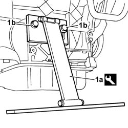
1. Fit the rear power unit mounting bracket (1a) and secure it to the engine block using the fixing bolts (1b) using the existing threaded openings.
| Description | Code | Function | |
|---|---|---|---|
| 1a | Engine mounting bracket | 1.870.868.001 | Removing power unit support |
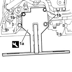
1. Fit the front power unit mounting bracket (1a) and secure it to the engine block using the fixing bolts (1b) using the existing threaded openings.
| Description | Code | Function | |
|---|---|---|---|
| 1a | Engine mounting bracket | 1.870.900.000 | Removing power unit support |
1. Position the tool for supporting the power unit whilst removing and refitting (1a) on the hydraulic lift (1b).
| Description | Code | Function | |
|---|---|---|---|
| 1a | Tool for removing and refitting power unit | 1.870.835.002 | Removing power unit support |
| Description | Code | Function | |
|---|---|---|---|
| 1b | Support | 1.870.835.001 | Removing power unit |
2. Fasten the mounting brackets (2a) and (2b) to the tool for removing and refitting the power unit.
3. Check that the support pins and blocks are positioned correctly and in contact with the power unit.
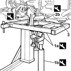
Completely lower the power unit hydraulic support and the lift.
Op. 1008C10 POWER UNIT UPPER REACTION LINK R R
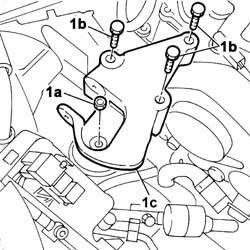
1. Undo the nut (1a) and the bolts (1b), then remove the timing side rigid power unit support (1c).
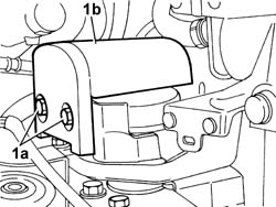
1. Undo the fixing bolts (1a) and remove the damper mass (1b).
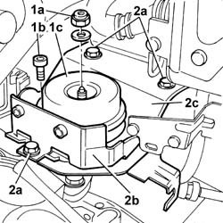
1. Undo the nut (1a) and the bolts (1b) and remove the gearbox side flexible mounting (1c).
2. Undo the fixing bolts (2a) and remove the support for the damper mass (2b) and the gearbox side power unit support (2c).
1. Manoeuvre the power unit turning it, then remove it from the engine compartment.
Take the greatest care not to damage the parts fitted to the vehicle whilst rotating the engine and removing the power unit.
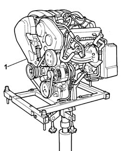
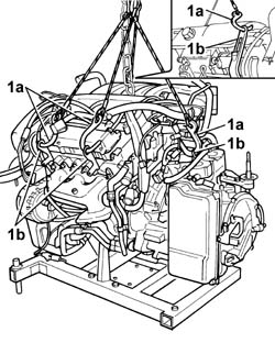
1. Secure the power unit to a lifting device, using the hooks (1a) fitted in the special mounting points (1b), undo the bolts fixing the support tool to the hydraulic lift and place the power unit on a support.
Refitting
Position the power unit, supported by the support tool on the hydraulic lift.
Manoeuvre the power unit turning it, then place it in the the engine compartment.
Take the greatest care not to damage the parts fitted to the vehicle whilst rotating the engine and positioning the power unit.
Position the gearbox side power unit mounting and the damper mass support, then tighten the fixing bolts to the recommended torque.
| Value daNm | Fastening | Component | Ø | |
|---|---|---|---|---|
| 2,5 | Bolts | POWER UNIT WITH AUTOMATIC TRANSMISSION |
Position the flexible mounting and tighten the fixing bolts to the recommended torque.
| Value daNm | Fastening | Component | Ø | |
|---|---|---|---|---|
| 3 | Bolts | POWER UNIT WITH AUTOMATIC TRANSMISSION |
Tighten the nut fixing the flexible mounting to the gearbox side support to the recommended torque.
| Value daNm | Fastening | Component | Ø | |
|---|---|---|---|---|
| 6,5 | Nut | POWER UNIT WITH AUTOMATIC TRANSMISSION |
Position the damper mass and tighten the fixing bolts.
Lift the power unit hydraulic support, position the timing side rigid power unit support and tighten the nut and the bolts to the recommended torque.
| Value daNm | Fastening | Component | Ø | |
|---|---|---|---|---|
| 4,5 | Nut | RIGID ENGINE MOUNT, TIMING SIDE |
| Value daNm | Fastening | Component | Ø | |
|---|---|---|---|---|
| 6 | Bolts | RIGID ENGINE MOUNT, TIMING SIDE |
Op. 1008C10 POWER UNIT UPPER REACTION LINK R R
Undo the bolts fixing the mounting brackets to the tool for removing and refitting the power unit and remove the support assembly from underneath the vehicle.
| Description | Code | Function | |
|---|---|---|---|
| Support | 1.870.835.001 | Removing power unit |
| Description | Code | Function | |
|---|---|---|---|
| Tool for removing and refitting power unit | 1.870.835.002 | Removing power unit support |
Undo the retaining bolts and remove the front power unit mounting bracket.
| Description | Code | Function | |
|---|---|---|---|
| Engine mounting bracket | 1.870.900.000 | Removing power unit support |
Undo the retaining bolts and remove the rear power unit mounting bracket.
| Description | Code | Function | |
|---|---|---|---|
| Engine mounting bracket | 1.870.868.001 | Removing power unit support |
Position the engine oil heat exchanger and tighten the pin to the recommended torque.
| Value daNm | Fastening | Component | Ø | |
|---|---|---|---|---|
| 5 | Pin | ENGINE OIL HEAT EXCHANGER |
Connect the supply and return pipes to the heat exchanger and refit the securing bands using the special tool.
| Description | Code | Function | |
|---|---|---|---|
| Caliper | 1.881.138.000 | Band opening |
Fit the engine oil filter element and tighten it in the housing.
Position the support for the lower centre reaction rod on the engine and tighten the fixing bolts to the recommended torque.
| Value daNm | Fastening | Component | Ø | |
|---|---|---|---|---|
| 4,5 | Bolts | POWER UNIT WITH AUTOMATIC TRANSMISSION |
Position the lower centre reaction rod and tighten the bolt fixing it to the bodyshell to the recommended torque.
| Value daNm | Fastening | Component | Ø | |
|---|---|---|---|---|
| 9 | Bolts | POWER UNIT WITH AUTOMATIC TRANSMISSION |
Tighten the bolt fixing the lower centre reaction rod to the support to the recommended torque.
| Value daNm | Fastening | Component | Ø | |
|---|---|---|---|---|
| 6,5 | Nut | POWER UNIT WITH AUTOMATIC TRANSMISSION |
Fit the end of the right driveshaft in its housing in the differential and tighten the bolts securing it to the mounting.
Position the heat shield and tighten the fixing nuts to the recommended torque.
| Value daNm | Fastening | Component | Ø | |
|---|---|---|---|---|
| 1 | Bolts | POWER UNIT WITH AUTOMATIC TRANSMISSION |
Fit the end of the right driveshaft in the housing in the hub and tighten the bolts fixing the steering knuckle to the shock absorber to the recommended torque.
| Value daNm | Fastening | Component | Ø | |
|---|---|---|---|---|
| (Shock absorber) 9 | Bolts | FRONT HUB STRUT |
Tighten the fixing nut to the recommended torque, position the safety cage and fit the split pin.
| Value daNm | Fastening | Component | Ø | |
|---|---|---|---|---|
| 10 | Nut | FRONT HUB STRUT |
Position the ABS cables for the brake pad wear sensor and the brake control pipe on the mounting brackets.
Working on the left side of the vehicle:
Fit the end of the inner constant velocity joint in the housing in the differential.
Tighten the bolts fixing the steering knuckle to the shock absorber to the recommended torque.
| Value daNm | Fastening | Component | Ø | |
|---|---|---|---|---|
| (Shock absorber) 9 | Bolts | FRONT HUB STRUT |
Position the ABS cables for the brake pad wear sensor and the brake control pipe on the mounting brackets.
Working on both sides of the vehicle:
Fit the steering track rod ends and tighten the nuts fixing them to the steering knuckles to the recommended torque.
Always replace the self-locking nuts with new ones.
| Value daNm | Fastening | Component | Ø | |
|---|---|---|---|---|
| 7 | Nuts | ADJUSTABLE STEERING ROD ENDS - R.R. |
Screw in the automatic transmission fluid drain plug and tighten it to the recommended torque.
| Value daNm | Fastening | Component | Ø | |
|---|---|---|---|---|
| 4.5 | Plug | AUTOMATIC TRANSMISSION FLUID - Change |
Op. 1048A23 COLD AIR INTAKE - R R
Op. 7055B65 ENGINGE BAY DUSTGUARD PROTECTION IN LEFT FRONT WHEEL ARCH R R
Op. 1080B39 RIGHT CATALYTIC PRECONVERTER R R OR REPLACE CYLINDER HEAD GASKET
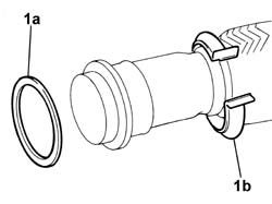
1. Replace the gasket (1a) and the band (1b) connected to the right pre-catalyzer pipe.
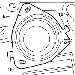
1. Replace the gasket (1a) between the exhaust manifold and the pre-catalyzer and bend the tabs (1b) behind the exhaust manifold flange to secure it in the correct fitting position.
1. Do not distort the front flexible pipe beyond the angular value of X = 20° and the cutting value of Y = 25 mm.
The front flexible pipe should be protected against all mechanical attack from the outside. It should not come into contact with corrosive products; the front flexible pipe cannot withstand any distortion when it is in position.
Failure to follow these precautions will result in the shortening of the life of the flexible pipe; separation or dismantling the exhaust line is compulsory for operations that require the power unit to be raised.
1. Fit the band secured to the right pre-catalyzer exhaust pipe and tighten it.
Ensure that the bolt is correctly fitted.
Lower the vehicle.
Tighten the nuts fixing the precatalyzer to the exhaust manifold to the recommended torque.
Replace the nuts fixing the precatalyzer to the exhaust manifold with new parts.
| Value daNm | Fastening | Component | Ø | |
|---|---|---|---|---|
| 3,3 | Nuts | LEFT CATALYTIC PRECONVERTER - R.R. |
Position the heat shield on the left exhaust manifold and tighten the fixing bolts.
Renew the clips retaining the supply pipe to the power assisted steering box.
Tighten the connector and connect the power assisted steering box supply pipe to the power assisted steering pump.
Tighten the bolts fixing the pipe mounting brackets to the front engine mountings.
Connect the power assisted steering fluid return pipe to the pump and refit the retaining band using the special tool.
| Description | Code | Function | |
|---|---|---|---|
| Caliper | 1.881.138.000 | Band opening |
Connect the electrical connection for the power assisted steering fluid pressure sensor.
| Description | Connector | |
|---|---|---|
| Steering pressure sensor | Vedere K058 SENSORE PRESSIONE STERZO |
Remove the protection for the end of the pipes and from the seats in the compressor.
Replace the gaskets at the end of the pipes.
Fit the end of the pipes on the compressor and tighten the retainining bolt.
Connect the vacuum intake pipe between the intake chamber and the brake servo to the rapid connectors.
Connect the passenger compartment heater coolant supply and return pipes to the rapid connectors on the bulkhead.
Connect the coolant supply pipe to the passenger compartment heater and refit the retaining band using the special tool.
| Description | Code | Function | |
|---|---|---|---|
| Caliper | 1.881.138.000 | Band opening |
Connect the coolant return pipe from the automatic transmission fluid heat exchanger and refit the retaining band using the special tool.
| Description | Code | Function | |
|---|---|---|---|
| Caliper | 1.881.138.000 | Band opening |
Connect the connector for the solenoid valve unit and the connector for the gear selector wiring.
| Description | Connector | |
|---|---|---|
| Automatic transmission solenoid valves | See L050 Automatic transmission solenoid valves |
Gear controls H037
Position the wiring and tighten the fixing bolt for the retaining band.
Connect the end of the bowden cable to the gear selector lever.
Remove the lever lock positioned previously.
Position the mounting bracket complete with gear selector bowden cable and tighten the fixing bolts.
Position the automatic transmission earth lead and tighten the fixing bolt.
| Description | Connector | |
|---|---|---|
| Left front earth | C010B |
Connect the electrical connections to the injection/ignition system control unit.
| Description | Connector | |
|---|---|---|
| Engine management control unit | M010B |
| Description | Connector | |
|---|---|---|
| Engine management control unit | M010C |
Position the wiring earth terminal and tighten the fixing bolt.
| Description | Connector | |
|---|---|---|
| Left front earth | C010A |
Position the engine management control unit guard and tighten the fixing bolts.
Position the wiring and tighten the retaining band fixing bolts.
Connect the electrical connection to the engine rpm sensor located on the bellhousing by the flywheel.
| Description | Connector | |
|---|---|---|
| Rpm sensor | See K046 Rpm sensor |
Connect the electrical connection to the engine coolant temperature sensor.
| Description | Connector | |
|---|---|---|
| Engine coolant temperature sensor/sender unit | See K036 Engine coolant temperature sensor/sender unit |
Position the wiring and tighten the fixing bolt for the retaining band.
Working on the right head, flywheel side, connect the electrical connection for the lower Lambda sensor on the pre-catalyzer and secure the connector.
| Description | Connector | |
|---|---|---|
| Lambda sensor on catalyzer - 2 | See K018 Lambda sensor on catalyzer - 2 |
Working on the right head, flywheel side, disconnect the electrical connection for the lower Lambda sensor on the left pre-catalyzer.
| Description | Connector | |
|---|---|---|
| Lambda sensor on catalyzer | See K017 Lambda sensor on catalyzer |
Working on the right head, timing side, disconnect the electrical connection for the upper Lambda sensor on the left pre-catalyzer.
| Description | Connector | |
|---|---|---|
| Lambda sensor on pre-catalyzer | See K015 Lambda sensor on pre-catalyzer |
Connect the electrical connection to the fuel vapour cut out valve, connect the vapour recovery pipe and position the valve on the mounting bracket.
Op. 1040B32 FUEL FILLER PIPE UNION SLEEVE - R + R
| Description | Connector | |
|---|---|---|
| Fuel vapour recovery solenoid valve | See L010 Fuel vapour recovery solenoid valve |
Connect the electrical connections for the engine wiring and the two-way connector, then secure the wiring.
| Description | Connector | |
|---|---|---|
| Engine compartment junction unit | B001B |
| Description | Connector | |
|---|---|---|
| Engine compartment junction unit | B001D |
Connect the end of the starter motor lead, tighten the fixing nut, then position the wiring and secure it.
| Description | Connector | |
|---|---|---|
| Engine compartment junction unit | B001A |
Fit the engine compartment junction unit protective cover in the engine compartment.
Op. 1088B10 ENGINE COOLING TANK - R + R
Op. 7210E22 WINDSCREEN BASE TRIM
Op. 5050B34 WINDSCREEN WIPER ARM/S COMPLETE WITH BLADE - R+R
Op. 5010B18 CLIMATE CONTROL UNIT AIR INTAKE - R.R.
Op. 4130B12 POWER STEERING FLUID RESERVOIR MOUNTING/BRACKETS - POSITION
Op. 4130B10 POWER STEERING FLUID RESEVOIR R R
Fit the air filter casing mounting bracket complete with mechanical vehicle lifting device and tighten the nuts and bolt.
Secure the end of the air filter casing cold air intake flexible pipe to the support.
Op. 1048A10 AIR CLEANER FILTERING ELEMENT - REPLACE
Op. 1048A47 SLEEVE FROM RIGID PIPE TO THROTTLE BODY - R R
Position the lower crossmember and tighten the fixing bolts to the recommended torque.
| Value daNm | Fastening | Component | Ø | |
|---|---|---|---|---|
| 8 | Bolt | COOLANT RADIATOR SUPPORT BEAM |
Position the power assisted steering system pipes complete with mounting brackets on the lower crossmember and tighten the fixing bolts.
Position the radiator-fans-condenser assembly in the housing and tighten the fixing bolts.
Replace the gasket and connect the lower pipe to the air conditioning system condenser and tighten the fixing bolt.
Replace the gasket and connect the upper pipe to the air conditioning system condenser and tighten the fixing bolt.
Connect the coolant supply pipe to the automatic transmission fluid heat exchanger and refit the retaining band using the special tool.
| Description | Code | Function | |
|---|---|---|---|
| Caliper | 1.881.138.000 | Band opening |
Connect the coolant supply pipe to the automatic transmission fluid heat exchanger to the radiator and refit the retaining band using the special tool.
| Description | Code | Function | |
|---|---|---|---|
| Caliper | 1.881.138.000 | Band opening |
Connect the upper coolant supply pipe from the manifold to the radiator refit the retaining band using the special tool.
| Description | Code | Function | |
|---|---|---|---|
| Caliper | 1.881.138.000 | Band opening |
Connect the coolant supply pipe from the radiator to the manifold and refit the retaining band using the special tool.
| Description | Code | Function | |
|---|---|---|---|
| Caliper | 1.881.138.000 | Band opening |
Position the relay control unit, tighten the fixing bolts and refit the wiring retaining bands.
Connect the electrical connections for the radiator fans, then position the wiring and secure it to the mounting bands.
| Description | Connector | |
|---|---|---|
| Engine fan motor | See N011 |
| Description | Connector | |
|---|---|---|
| Engine fan motor - 2 | See N012 |
Connect the electrical connection for the bonnet opening switch, incorporated in the actual lock, then position the wiring and secure it to the retaining bands.
| Description | Connector | |
|---|---|---|
| Bonnet release switch | See I010 Bonnet release switch |
Fit the bonnet lock and tighten the fixing bolts.
Connect the bonnet release control cable to the lock.
Adjust the bonnet lock following the instructions in operation 7025A10
Fit the lower crossmember and tighten the fixing bolts to torque.
Fit the upper front sacrificial crossmember and tighten the fixing nuts to torque.
Position the headlamp washer fluid supply pipe on the upper front crossmember and secure it to the retaining bands.
Op. 5540B78 LEFT FRONT LIGHT CLUSTER WITH TURN SIGNAL AND FOGLAMP R R
Op. 5540B79 RIGHT FRONT LIGHT CLUSTER WITH TURN SIGNAL AND FOGLAMP R R
Op. 7055B54 UNDER-ENGINE GUARD - R R
Op. 7055B90 LEFT FRONT WHEEL ARCH LINER - R.R.
Op. 7055B91 RIGHT FRONT WHEEL ARCH LINER - R.R.
Op. 4450B12 FRONT OR REAR WHEELS (TWO) - R+R
Connect the negative battery terminal.
| Description | Connector | |
|---|---|---|
| Battery | A001B |
Op. 0010T84 COOLANT FOR AIR CONDITIONING SYSTEM DEHYDRATE AND RECHARGE
Op. 0010T70 POWER ASSISTED STEERING FLUID - REPLACE
Op. 0010T45 AUTOMATIC TRANSMISSION FLUID - CHECK LEVEL AND TOP UP IF NECESSARY
Op. 0010T20 COOLANT CHECK DENSITY AND TOP UP IF NECESSARY
Op. 0010T11 ENGINE OIL CHECK LEVEL AND TOP UP
Remove the vehicle from the lift.
Parts & tools for this job Staging For 2002 Fiat Ulysse
- PARTTransmission filter kitSearch: Fiat Ulysse 2002 transmission filter kit
- FLUIDAutomatic transmission fluidSearch: Fiat automatic transmission fluid
- TOOLFluid transfer pumpSearch: fluid transfer pump
Links open Amazon search results in a new tab. As an Amazon Associate I earn from qualifying purchases.